ENGLISH
Pag. 27
THIS TECHNICAL MANUAL DESCRIBES THE PRODUCT AND ITS COMPONENTS, THE INSTALLA-
TION AND THE OPERATION OF THE SYSTEM. FOR INFORMATION AND INSTRUCTIONS ON THE
CONFIGURATION SOFTWARE, PLEASE REFER TO THE SEPARATE MANUAL.
1. Introduction
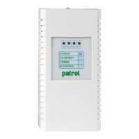
The highly innovative and versatile PL4 +D gas control unit is the ideal solution for small
systems with up to 12 gas detectors.
The system provides for the direct connection of 4 detectors to the gas unit (4-20mA) and
to additional 8 detectors that can be connected directly to the RS485 bus or via a remote
module with 8 x STG/IN8S inputs (optional).
Each input can be congured for dierent types of gas: toxic, refrigerant, ammable, and
oxygen, both for their deciency and enrichment.
The backlit display oers an accurate indication of gas concentration and allows the display
of established alarm levels.
The gas control unit manages up to 21 relay outputs, of which 5 are on board the gas control
unit and the other 16 are via STG/OUT16S and STG/8REL cards (optional).
The housing of gas control unit is a plastic box 9 DIN module. A further plastic box, 12 DIN
module can be supplied as optional.
The gas control unit power is 24Vdc (power sully available on request).
The PL4+D control panel has been designed to comply with the SIL1 safety functional requi-
rements.
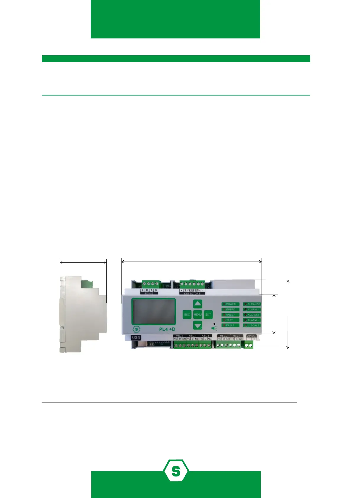
90,00 mm
45,00 mm
IMPORTANT!
Figure 1) Global dimensions PL4 +D
Table 1) Overview of devices connectable to the PL4 +D gas control unit. The numbers with the (*) indication are available through additional
modules.
Gas control
model
Nr. serial
bus RS485
Nr. max
detectors
Nr. max
outputs
STG/IN8S
Nr. max modules
STG/OUT16S
Nr. max modules
PL4 +D 1 4+8(*) 5+16(*) 1 1
Other features of the PL4 +D gas control unit are:
³ Event log can be displayed on the screen or downloaded to a PC.
³ USB port for PC connection for programming and control via specic software.