ENGLISH
Pag. 34
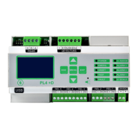
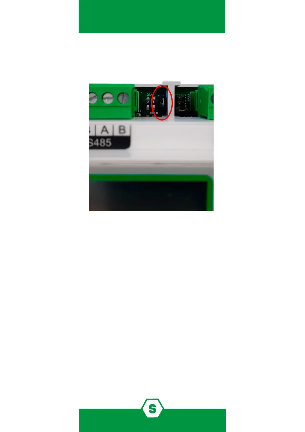
2.6 JP27 connector
If the JP27 connector is closed, the line terminator is enabled. It’s important to maintain
always this conguration.
Figure 9) Always keep JP27 closed
2.7 Field device connections
The gas control unit has one RS485 data bus to which 8 gas detectors can be connected. The
gas detectors are connected through the serial bus (directly in the serial RS485 if equipped
with serial output or through one module with 8 STG/IN8S inputs if of type 4-20 mA) and the
STG/OUT16S output module. The maximum length of each serial data bus is 800 m.
To connect devices, four conductors are required (intended both as detectors with a serial
output as well as IN and OUT modules): two for the RS485 serial bus and two for powering
the devices. For this reason, two dierent wires must be used or a single wire that has sui-
table characteristics, as described below.
³ The RS485 serial bus must be connected with an EIA RS 485 connection wire: No. 2 wi-
res with 0.22/0.35 mm2 section with shield (TWISTED PAIR). Nominal capacity between
conductors < 50 pF/m, nominal impedance 120 ohm. Total line length with this type
of connection must not exceed 1,000 metres. An example of a recommended cable is
a BELDEN 9841 or similar wire (EIA RS485 data transmission wire). Only connect detec-
tors (and IN and OUT modules) in a “cascading” manner. Avoid tree or star connections
since they reduce interference immunity.