ENGLISH
Pag. 45
3.2 System status
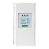
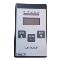
The gas control unit communicates with the operator by means of the LCD display and LEDs
on the front panel. Dierent information is displayed during dierent states of the system. A
few general rules apply at any level as follows:
³ The page scrolling can be done using the up/down arrow keys.
³ The up/down arrow keys allow the user to move between editable parameters in the
various menus.
³ At any display level, the ESC key will switch back to the previous view.
³ On any screen, if no key is pressed for 3 minutes, the display indication will automati-
cally return to the main screen.
The system is designed to be in one of the following operating status:
³ NORMAL
³ ALARM
³ FAULT
³ TEST
³ UNSET
³ EMERGENCY
NORMAL
It is the normal system operating status without alarms and faults. The screen in this status
displays the channels (gas detectors) with gas concentration measured in real time (see g.
21).
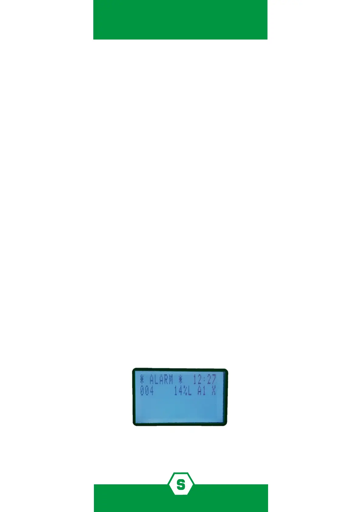
ALARM
The Alarm status is activated when one or more gas detectors measure a gas concentration
higher than the alarm threshold set during the conguration of the gas control unit. Pro-
gramming of alarm thresholds and other parameters of each channel can be set during PC
conguration.
In the alarm window the following info is available:
Figure 22) Screen in Alarm status
If there are Alarms from multiple gas detectors the, the alarm screen will present the infor-
mation of the dierent channels in the following manner: