ENGLISH
Pag. 40
2.9 STG/IN8S remote input modules
STG/IN8S remote modules are eld mounted and connected to the gas control unit via
RS485 buses. They are used to connect 8 x 4-20mA analogue gas detectors. Each module
must be addressed using the rotary switches on the PCB. The address must be univocal and
between 1 and 255 (1-247 for Modbus protocol). See the summary table 1 for the maximum
number of connectable modules to the gas control unit.
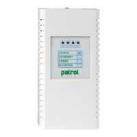
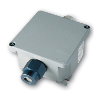
Figure 14) STG/IN8S module
2.10 STG/OUT16S remote output modules
STG/OUT16S remote modules are eld mounted and connected to the gas control unit via
RS485 buses. They provide 16 Open Collector outputs (negative switch) with a program-
mable function for the remote activation of sirens, solenoid valves, relays, etc. Up to 2 8-relay
boards can be connected to each STG/OUT16S module, transforming the output from Open
Collector to a voltage-free exchange contact. See the summary table 1for the maximum
number of connectable modules to the gas control unit.
Each module must be addressed using the rotary switches on the PCB. The address must be
univocal and between 1 and 255 (1-247 for the Modbus protocol).
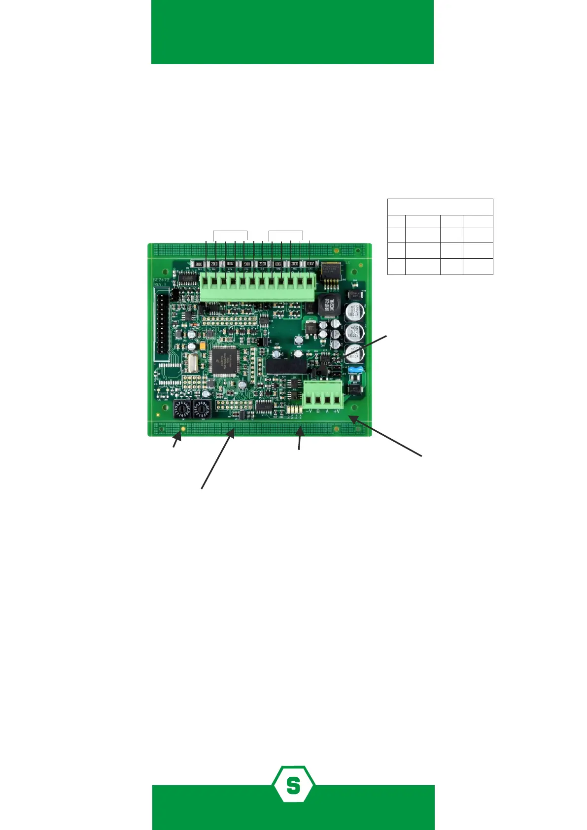
Jumpers not to be touched
JP1
JP2
JP3
JP4
JP9
JP11
JP12
JP14
Closed
Open
Open
Open
Closed 1-2
LED
DL1: WD Fault
DL2: TX Data
DL3: RX Data
DL4: RTS
JP10
EOL resistor
If the module is the last of the
bus line, close JP10
Power supply (-V/+V)
RS485 serial line (B/A)
JP13 Communication Baud Rate setting:
Closed 115.000 bps (PL4+D control panel)
Open 9.600 bps (old Galileo Multiscan control panel)
Channels 5-8
Channels 1-4
-V
+V
-V
+V
Gas detector connections
Open
Rotary switches for
the module address
Open
Open