ENGLISH
Pag. 31
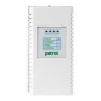
2.2 Unit diagram and part identication
Figure 5) Part identication
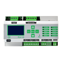
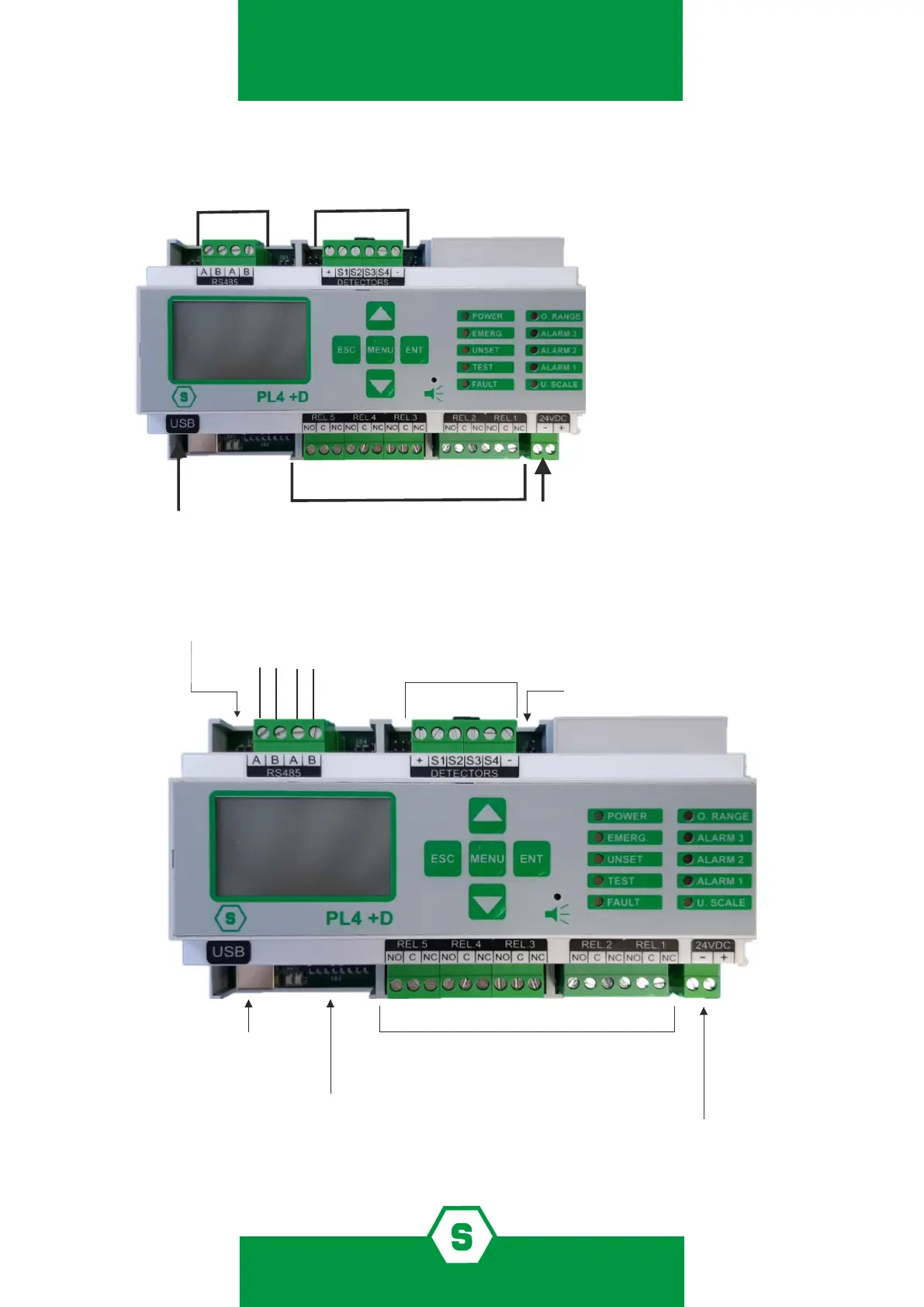
2.3 Layout PL4 +D gas control unit
Figure 6)
1. Power Supply (24 Vdc)
2. Relay outputs (5)
3. USB port
4. RS485 bus connection
5. 4 inputs 4-20 mA
SD3: dip switch for language setting
4 x 4-20 mA ANALOG INPUTS
5 RELAY OUTPUTS
RS485 SERIAL LINE
USB FOR PC
CONNECTION
POSITIVE AND NEGATIVE FROM POWER SUPPLY 24 Vdc
A
B
5 4 3 2 1
+
-
NO: Normally Open
C: Common
NC: Normally Closed
JP25: JP1-2 closed
SD2: dip switch for Baud Rate
A
B