ENGLISH
Pag. 29
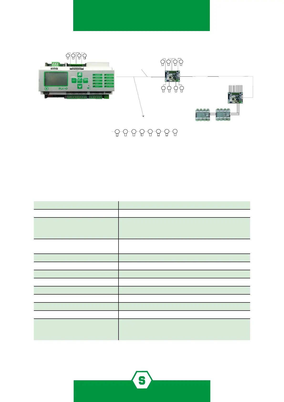
1.3 Block diagram system with PL4 +D gas control unit
Figure 2) System block diagramTechnical specications
1.4 Technical specication
Table 4) Technical specications PL4+D
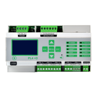
Housing IP65 plastic box, 9 DIN module
Inputs Max. 12 detectors
Outputs 5 relays in the gas control unit
16 O/C or relay outputs via the STG/OUT16S and ST-
G/8REL remote cards.
Serial ports 1 x RS485
1 x USB (PC connection)
Power 24Vdc
Absorption Max 10 VA
Display Liquid crystal display (LCD)
Optic indications 10 LEDS
Working temp. 0/-55°C
Storage temp. -20 ÷ +60 C°
Working RH 15-85%
Storage RH 5-85% (non-condensing)
ATEX conformity II(2)G [Ex Gb] II *
EN 60079-0:2018
EN 60079-29-1:2016
* The control unit is intended for use outside the explosive atmosphere connected to gas
detectors in a potentially explosive area
LOOP
(6)
RS485
option: the detectors could be connected
directly on the loop in daisy-chain mode
(1) 4-20 mA ANALOG GAS DETECTORS
(2) ANALOG 8 INPUT MODULE STG/IN8S
(3) 2 TWISTED WIRES FOR THE RS485 BUS + 2 WIRES FOR THE POWER SUPPLY (12-24 Vdc)
(4) GAS DETECTORS WITH RS485 OUTPUTS
(5) 16 O/C OUTPUTS MODULE STG/OUT16S
(6) 8 RELAY STG/8REL MODULE
(1)
(2)
(3)
(4)
(5)
PL4 +D