3.7
3.2.1 Analogue Outputs
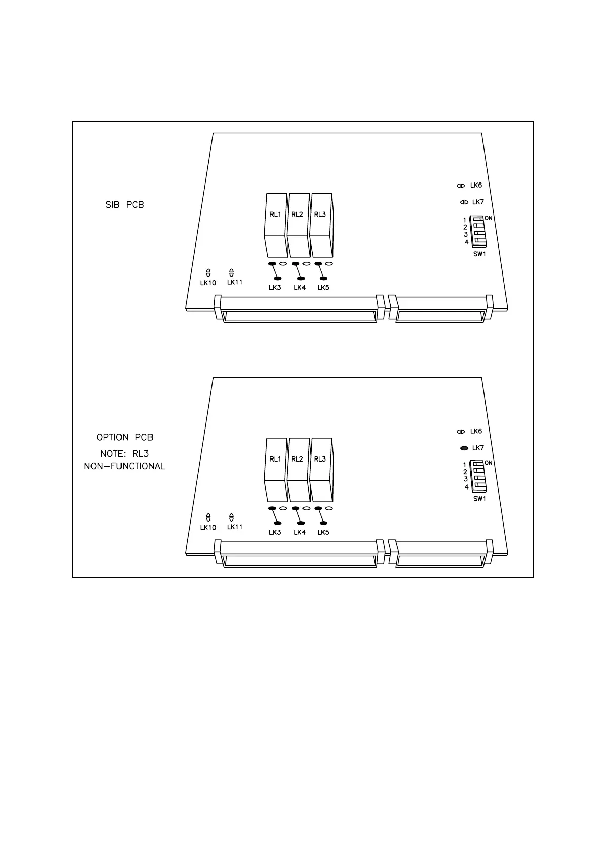
Figure 3.4 SIB and Optional Output PCB's
Each analogue output is supplied set for current output and may be configured by the
user to be 0-20mA or 4-20mA, and be assigned a particular range of operation, in
software. This is described in the Quickstart manual. In addition, a "Range 2" setting
for each analogue output can also be configured in software. Maximum impedance is
1k ohm for current output. If desired, each analogue output may be changed to voltage
output of either 0-10V or 2-10V, minimum impedance 1M ohms. This is done by
soldering links into position "LINK 10" and "LINK 11" on the relevant SIB (Sensor
Interface Board) PCB or Option PCB for the first and second analogue output
respectively. See Section 3.2.2. In every case, fit a suitable gland, insert, secure and
strip a suitable cable pair before connecting the cores to the appropriate terminals.

 Loading...


