3.10
3.2.3 Relay Outputs
User selection of NC or NO operation is described in Section 3.2.4. As with the
analogue outputs, each relay has its own software identity relating to the slot in which
the PCB, on which it is physically located, resides. The following tables show the
physical locations for connections to the relay outputs. All relay outputs are rated
240VAC/1.0A or 30VDC/1.0A. In each case, fit suitable glands and cable and connect
to the relevant terminals. Select the correct procedure according to the architecture.
*option PCB
Terminal locations are as illustrated in Figure 3.2.
3.2.4 Relay Output Link Selection
After connecting up the required relay output, the NC/NO selections may be altered on
the SIB PCB and (where fitted) output Option PCB(s). Refer to Figure 3.4 for general
schematic and carefully remove and replace the PCB as before, if a change is to be
made.
Normally Closed/Normally Open (NC/NO)
The factory setting of all relay output wire links is soldered in the NC position. This
means that the contacts will open to signal an alarm. The contacts will also be open if
there is no power applied to the 2500, i.e. they are fail-safe. If, however, it is required
to change to NO operation (i.e. close to signal an alarm) this can be done by cutting
and reordering the wire links as listed below.
NOTE
Each relay output is supplied set for NC (i.e. Normally Closed under "Safe"
condition) operation, and may be assigned to a particular alarm or signalling
function in software. This is described in the Quickstart manual.
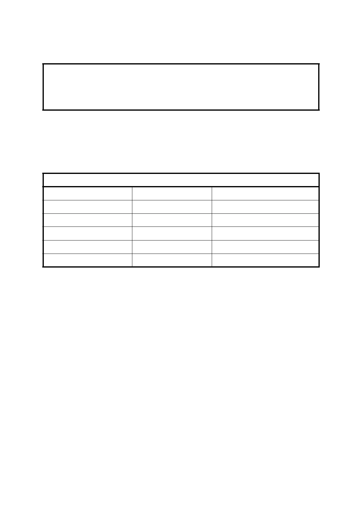
Table 3.2 – Relay Output Connections
Output Software ID Terminal Connections
Relay 1 1.3 TB 23-1 and TB 23-2
Relay 2 1.4 TB 23-3 and TB 23-4
Relay 3 1.5 TB 23-5 and TB 23-6
Relay 4* 2.3 TB 22-5 and TB 22-6
Relay 5* 2.4 TB 22-7 and TB 23-7

 Loading...


