3.23
3.5 Pressure Transducer Connections – (If Supplied)
The pressure transducer cabling is terminated to the source end right hand side (RHS)
of the analyser.
The pressure transducer is supplied pre-wired to the analyser. The cabling is
connected to PCB 02500911A TB35 as shown in Table 3.10
.
The general layout of the pressure transducer option is illustrated in Figure 3.6.
WARNING
Do not use an uncertified dcs, datalogger or printer in a hazardous area.
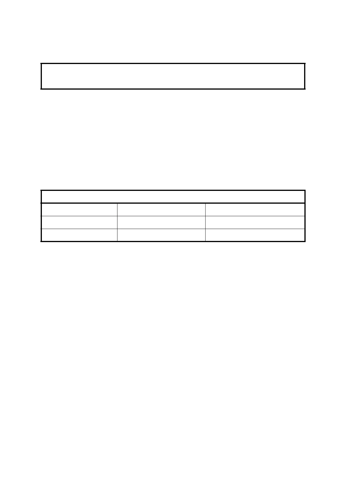
Table 3.10 – Pressure Transducer Connections
PCB 02500911A Interconnecting Cable Pressure Transducer
TB35 – 5 (signal +) Identified '1' Terminal 1 (+)
TB35 – 1 (signal -) Identified '2' Terminal 2 (-)

 Loading...


