3.16
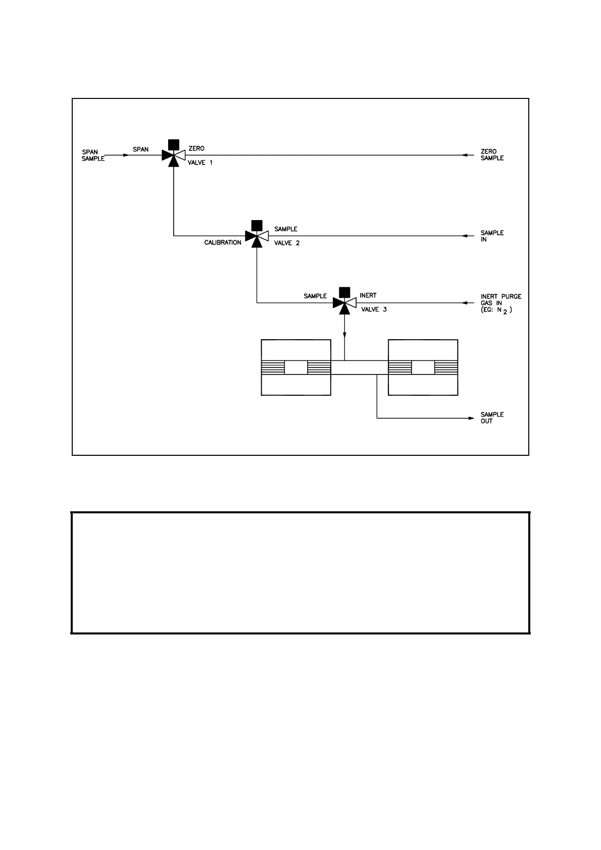
Figure 3.5 Autocalibration Valve Configuration
3.4 Digital Connections
Digital connections in RS/EIA-232 format are provided for attaching a local portable
printer to receive set-up information directly down loaded from the 2500, or to report
measurement and analyser status information to a DCS or datalogger.
3.4.1 RS-232 Connection
See the Quickstart manual for configuration of the RS-232 port and operation of this
function. See Figure 3.2 and Table 3.9 for connections. The format of the serial data
stream is as follows:
NOTE
All digital cables must have a braided overall screen or armour. The screen must be
terminated at the point of entry to the case. This will be by using a gland, which
makes a connection between the cable screen and the case. Beware of ground/earth
loops if the screens are also connected at the user end.
Where two cables are passed through a single entry, a metal gland specifically
intended for two separate cables shall be used.

 Loading...


