3.6
3.2 Signal Connections
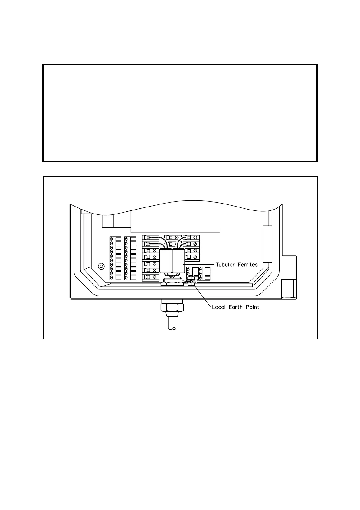
Figure 3.3 Signal Cable Connections
NOTE
All signal cables must have a braided overall screen or armour. The screen must be
terminated at the point of entry to the case. This will be by using a gland, which
makes a connection between the cable screen and the case. Beware of ground/
earth loops if the screens are also connected at the user end.
Where two cables are passed through a single entry, a metal gland specifically
intended for two separate cables shall be used.
To minimise the effects of interference from the RF fields, a Steward type 28B0562-
200 or equivalent ferrite sleeve (Servomex Part No. 2824-0017) shall be placed
over each mA output cable pair. Refer to Figure 3.3.

 Loading...


