3.15
3.3.7 Internally Powered Solenoid Valve Connections
Connect to solenoid valve relays SV1, SV2 and SV3 as detailed below. Take care to
ensure that internal 12VA (total) rating of the 24VDC supply is not exceeded.
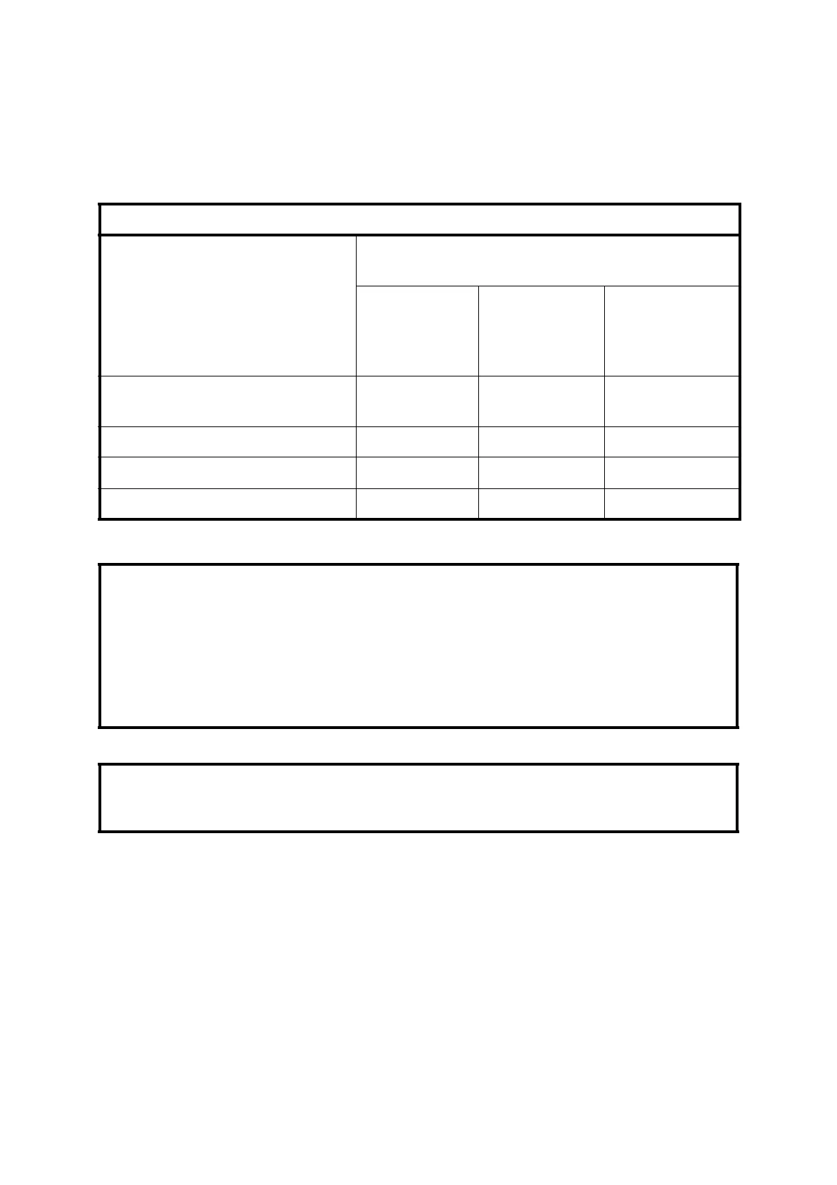
Table 3.5 – Internally Powered Solenoid Valve Connections
Valve State (ON=Current Flow Through
Solenoid)
Span/Zero
Valve SV1
TB34 – 1 (-)
TB36 – 6 (+)
Cal/Sample
Valve SV2
TB34 – 3 (-)
TB36 – 5 (+)
Sample/Inert
Valve SV3
TB34 – 5 (-)
TB36 – 5(+)
Cell or Chopper Box
Under Temperature
either either OFF(Inert)
NORMAL STATE OFF OFF (Zero) ON(Sample) ON(Sample)
Zero Sample Required OFF (Zero) ON(Cal.) ON(Sample)
Span Sample Required ON(Span) ON(Cal.) ON(Sample)
NOTE
To ensure internally powered solenoid valve function, fit links between:
TB34 – 2 and TB36 – 4
TB34 – 4 and TB36 – 3
TB34 – 6 and TB36 – 3
CAUTION
TB36 terminals 5 and 6 (+24V) are always live and should not be grounded.

 Loading...


