3.17
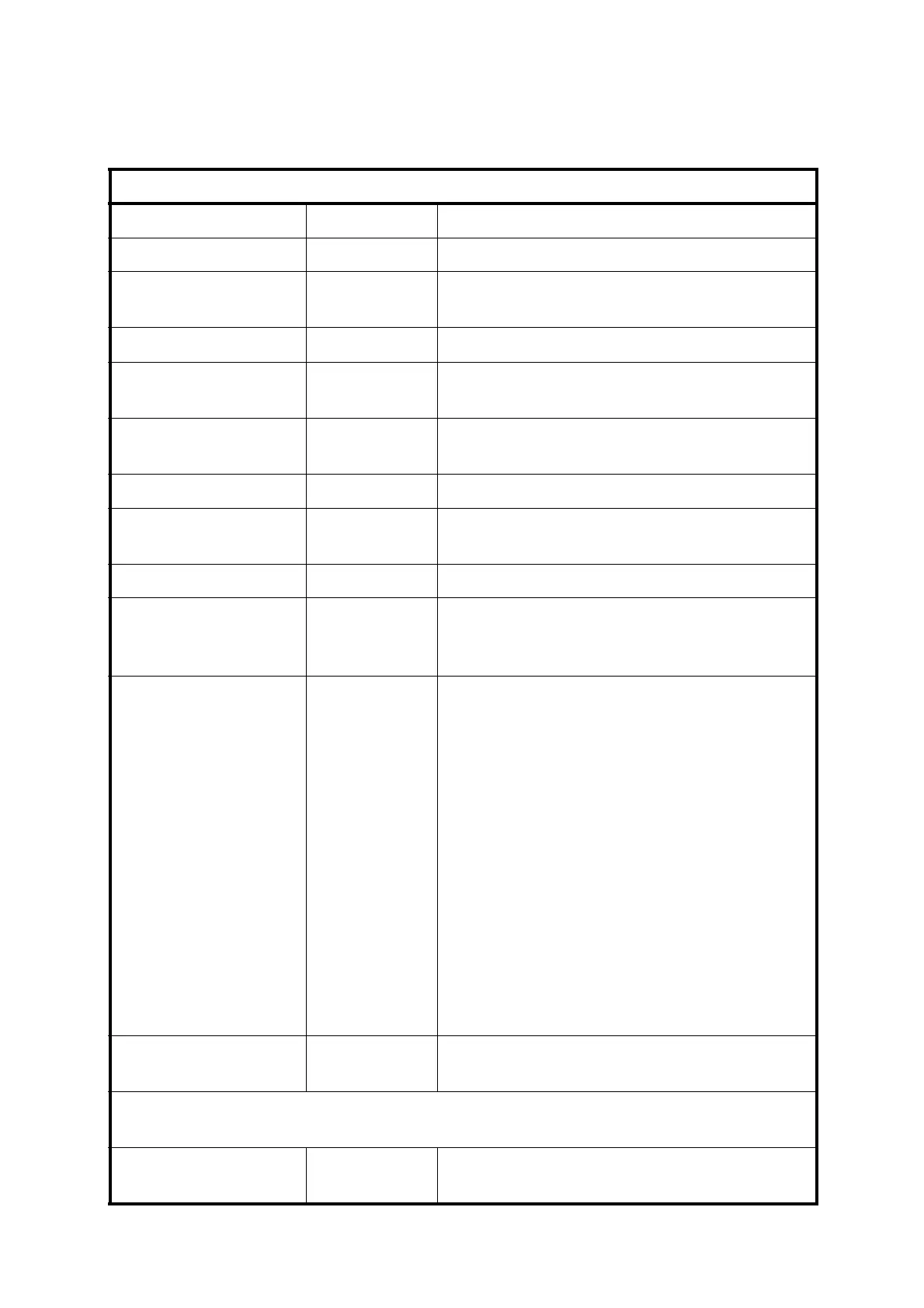
Table 3.6 – Serial Data Format
Item Size Description
<CR> 1 byte Carriage return character (ASCII code 13).
date; 8 bytes dd/mm/yy or mm/dd/yy depending on user
settings.
time; 8 bytes hh:mm:ss
number of
components
1 byte 1 byte Number of components fitted
(range 1-3)
<CR><LF> 2 bytes Carriage return and Line Feed characters
(ASCII codes 13 and 10 respectively).
component 1 formula; Max 6 bytes Chemical formula defined for component 1.
component 1
concentration;
Max 5 bytes Concentration for component 1 as defined
for measure display.
component 1 units; Max 3 bytes Units defined for component 1.
component 1 alarm
status;
4 bytes One byte for each alarm. Set to alarm
number (1,2,3 or 4) when alarm is raised,
<space> when alarm not raised
component 1
Autocalibration
status;
1 byte or
15 bytes
Indicates Autocalibration phase.
0 = Not in Autocalibration
1 = In span preflush
2 = In zero cal
3 = zero corrected. This is then followed by
two additional values, which are separated
by commas, each 6 bytes that represent the
zero before calibration and the zero after
calibration respectively.
4 = In span cal
5 = span corrected. This is then followed by
two additional values, which are separated
by commas, each 6 bytes that represent the
span before calibration and the span after
calibration respectively.
6 = In post flush
<CR><LF> 2 bytes Carriage return and Line Feed characters
(ASCII codes 13 and 10 respectively).
Note: The data for components 2 and 3 will only be present on a 2550
instrument.
component 2 formula; Max 6 bytes Chemical formula defined for component 2.
(if fitted)

 Loading...


