2.5
When mounting the analyser ensure that the panel or brackets employed are adequate
to take the weight and there is a minimum clearance above the casing of 500mm (20")
to provide space to open the end covers.
Fig 2.2 provides mounting details and a table of mounting hole spacings for the various
cell lengths. Be sure to identify the correct hole spacing.
When the 2500 is to be vertically mounted the display may be rotated 90° to bring it into
a legible position. This is done by removing the internal metal cover and ribbon cable
clamp, and removing the retaining bracket. The display unit can then be withdrawn a
little and rotated. Reassemble the disturbed components in reverse order, carefully
folding the ribbon cable to prevent any stress on it.
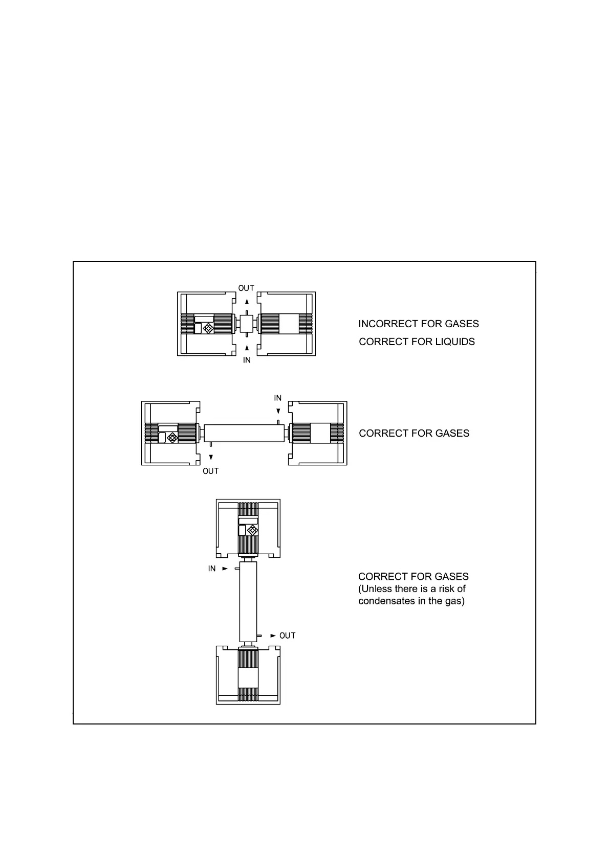
Figure 2.1 2500 Positioning Restrictions

 Loading...


