11
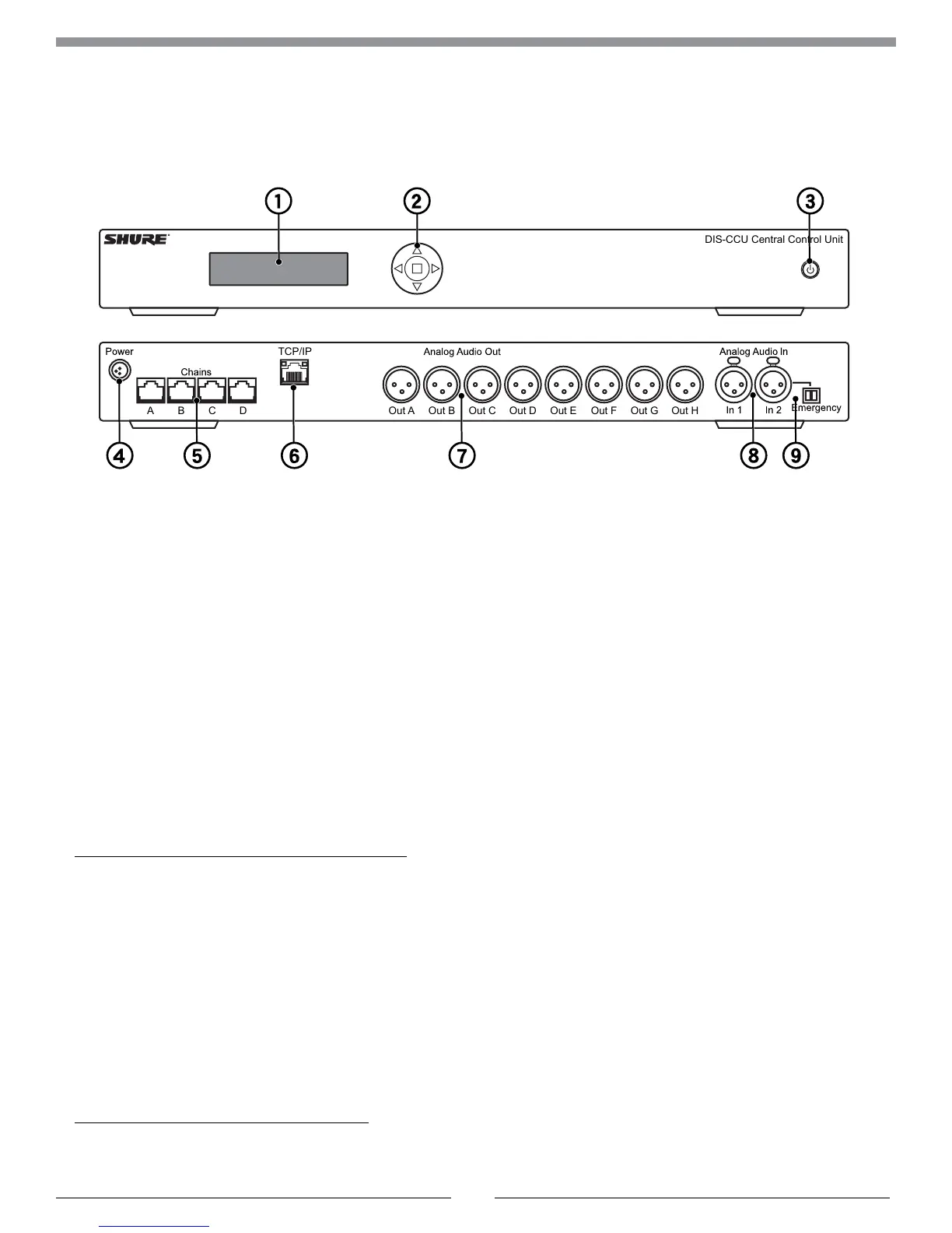
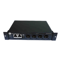
DIS-CCU Hardware Description
Out A Out B Out C Out D
DIS-CCU Central Control Unit
TCP/IP
Out E
A B C D
Out F Out G Out H
DIS-CCU Central Unit
Front Panel
① Menu display
A 2x20 character OLED-display enables system
configuration without a computer.
② Navigation Buttons
5-button keypad for configuring the system without a
computer.
③ Power Button
The power button turns on or off the central unit. All
connected DCS-LAN units and power supplies will
automatically power on or off with the CCU.
• Green = powered on
• Red = powered off but connected to power supply
• Off = no power supply is connected to the CCU
Note: System settings are stored and persist through a power cycle.
Back Panel
④ Power Supply Connector
Threaded connector secures to the PS-CCU power supply.
⑤ DCS-LAN Outputs
Four RJ45 jacks are available for connecting the
microphone units, forming the DCS-LAN. The DCS-LAN
chain safely carries digital audio, control data, and power
over the same cable. Use any or all of the four outputs for a
variety of layout configurations.
Important: Only connect DCS-LAN equipment to this output.
⑥ Control Connector (TCP/IP)
The RJ45 connector allows access to the built-in web
application from a computer, or for connection to a control
system like AMX
®
or Crestron
®
.
⑦ Audio Outputs
Eight balanced, male XLR connectors for connection to
PA systems, audio mixers, audio recorders, or a language
distribution system.
⑧ Audio Inputs
Two balanced, female XLR connector for adding external
audio equipment to the meeting, such as wireless
microphones, a teleconferencing system, processed audio
signals, an emergency broadcast message (EEM), or
music during meeting breaks. Input gain and volume are
adjust from the CCU front-panel or web application.
⑨ Emergency switch connector
Provides an emergency override signal in the event of
an emergency. When the connected switch is closed, the
audio signal on Input 2 is distributed to all output channels,
overriding all other audio inputs.