17
Connection Diagrams
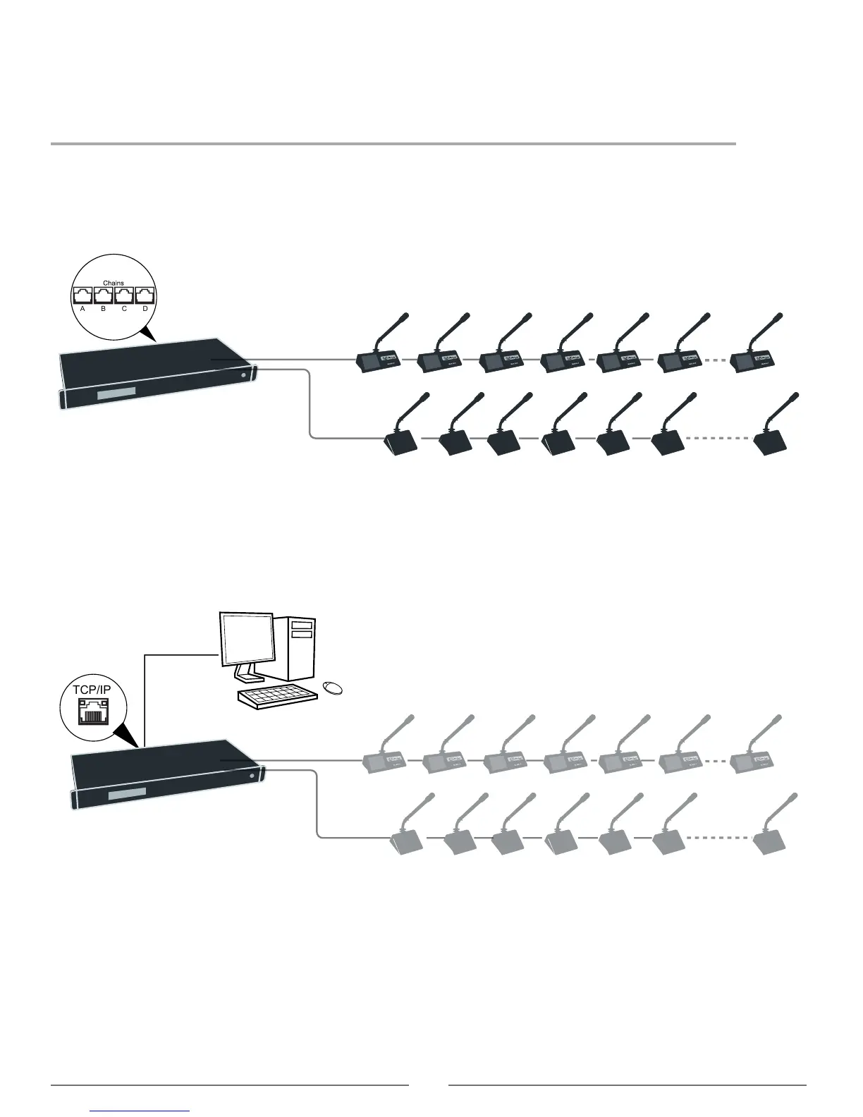
The following system diagrams illustrate typical hardware connections to the DIS-CCU central control unit. Actual
installations may use different combinations of hardware, but follow the general concepts outlined below.
Note: Flushmount and portable microphone units are interchangeable in the following drawings, unless noted.
Basic Setup with Microphone Units
The system is operational without the use of a computer. Use the CCU navigation screen to set up the installation.
Basic System with Multiple Chains
Computer for Advanced Control
Connect a computer to the central control unit for comprehensive management of the system through a web browser.
Connect an Ethernet cable from the dedicated TCP/IP port to a computer.
Computer Control
Connect the CCU TCP/IP port to computer