Complementary information
•
T
he module status bits have the following meanings:
°
0 = Error
°
1 = No error
•
If a module is not present, all bits of the module are set to logical 1.
•
Bits reserved for future use are always logical 1.
•
The status bytes of each module are transmitted as a 32-bit word in big endian
format, i.e. the most significant byte (MSB = byte 3) is transmitted first and the
least significant byte (LSB = byte 0) last.
13.3.1.2 Modbus® TCP holding register
13.3.1.2.1 Commands
The output data is written dynamically. From address 256, a client can, for example,
w
rite 25 words (50 bytes) of output data. From address 257, 24 words (48 bytes) of
output data can be written, and so on.
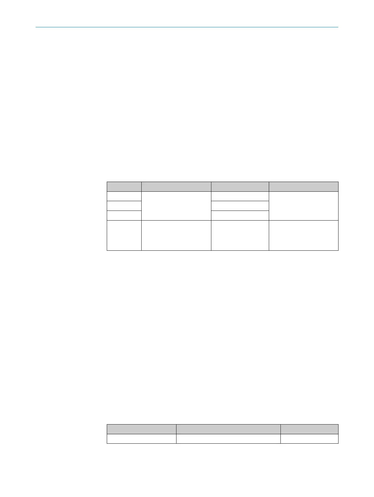
Table 170: Modbus® TCP – output data
Address Contents Size Description
256 Output data 1 word (2 bytes) Is specified in the higher-
le
vel controller.
… 1 word (2 bytes)
280 1 word (2 bytes)
356 Find me function 1 word (2 bytes, MSB
al
ways 0)
0: Standard operation of
the LEDs
1: Flash mode for 30 sec‐
onds
1)
1)
A change from 1 to 0 ends the flash mode.
13.3.2 SLMP
Overview
T
he safety controller supports an SLMP server without a safety protocol.
SLMP (Seamless Messaging Protocol) is used for communication in CC-Link systems.
SLMP allows you to read and write data ranges completely or only up to a smaller data
quantity (≤ total size).
Supported commands
•
0x0613 R
ead memory
•
0x1613 Write memory
•
0x0E30 Node search
13.3.2.1 SLMP input data
13.3.2.1.1 Process data to the higher-level controller
Process data to the higher-level controller
T
able 171: Process data to the higher-level controller
Address Contents Size
0 Configured process data 25 words (50 bytes)
You configure the contents in the configuration software.
TECHNICAL DATA 13
8024589/2020-11-10 | SICK O P E R A T I N G I N S T R U C T I O N S | Flexi Compact
143
Subject to change without notice