Complementary information
•
If t
here are objects in the area of the muting sensors during the first logic cycle
and therefore one or more muting sensor signal inputs are set to 1, this gener‐
ates a muting error. The signaling of the error state at the Muting error output is
suppressed if the BWS input = 1. Before a new valid muting cycle can be executed,
this error must be reset.
•
The muting times have an accuracy of ± 10 ms (evaluation plus logic execution
time).
Further topics
•
"Safety notes for muting applications", page 18
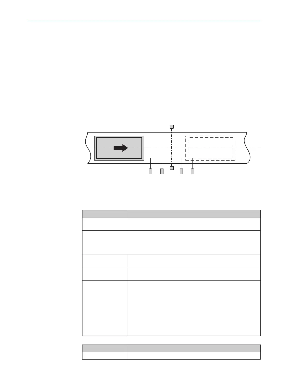
7.6.2.7.2 Sequential muting V1
Overview
Figure 46: Muting with two sensor pairs arranged in sequence (A1 / A2 and B1 / B2)
Principle of operation
T
able 112: Inputs
Input Description
ESPE Data type: Boolean
T
he input must be connected to the electro-sensitive protective device.
A1
A2
B1
B2
Data type: Boolean
S
ignal from the muting sensor
Override
(optional)
Data type: Boolean
"Input Override", page 100
Band signal
(opt
ional)
Data type: Boolean
"Input Band signal", page 103
C1
(opt
ional)
Data type: Boolean
The optional C1 input can be used as additional protection against
manipulation. If it is used, the C1 input must have switched to 0 after a
previous muting cycle, and to 1 at the latest when both muting sensor
signal inputs switch to 1 at the same time. A failure to meet this
condition results in a muting error, which is indicated at the Muting error
output.
The C1 input must then switch back to 0 before the subsequent muting
cycle is permitted. The C1 input is not relevant for the duration of the
muting status.
Table 113: Outputs
Output Description
Enable Data type: Boolean
CONFIGURATION 7
8024589/2020-11-10 | SICK O P E R A T I N G I N S T R U C T I O N S | Flexi Compact
95
Subject to change without notice