Product description
FLOWSIC100 Flare · Addendum to Operating Instructions · 8025365/V1-0/2020-05 · © SICK Engineering GmbH 23
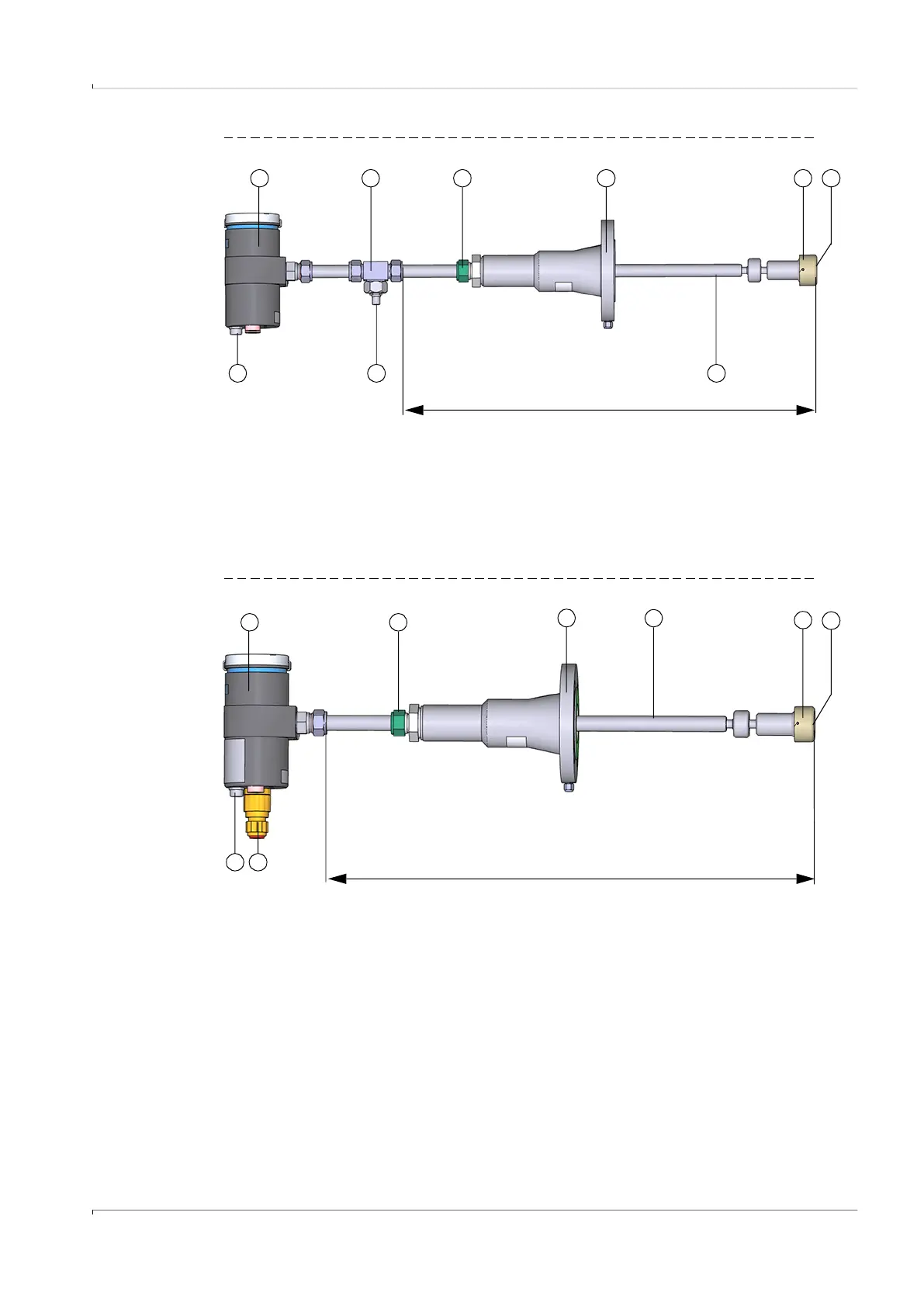
Fig. 6 F1F-M (only master shown)
Fig. 7 F1F-H (only master shown)
1 Pressure compensation element 6 Retraction nozzle
2 Electronics unit 7 Duct probe
3 T-connector 8 Sensor contour
4 TNC connector (connection for Slave) 9 Transducer
5 Self-cutting ring
1 7
86
4
532
Sensor length
9
3
7
5
1
42
Sensor length
1 Pressure compensation element 5 Retraction nozzle
2 Electronics unit 6 Duct probe
3 Cable gland (connection for Slave) 7 Sensor contour
4 Self-cutting ring 8 Transducer
6
8

 Loading...


