Installation
FLOWSIC100 Flare · Addendum to Operating Instructions · 8025365/V1-0/2020-05 · © SICK Engineering GmbH 39
Calculate transducer distance a with the Geometry Calculator
Alternatively to the manual calculation of the nozzle offset, the Geometry Calculator avail-
able on the provided product CD can be used,
p. 32, §4.5:
1 Open the Geometry Calculator.
2 On the tab "Calc transducer distance" first select in the field "Meter type" if it is a 1-path
or a 2-path installation.
3 Enter circumference U.
4 Enter the "Nominal nozzle angle" (e.g. 75°, 60°, 45°).
5 "Transducer Distance a" is calculated.
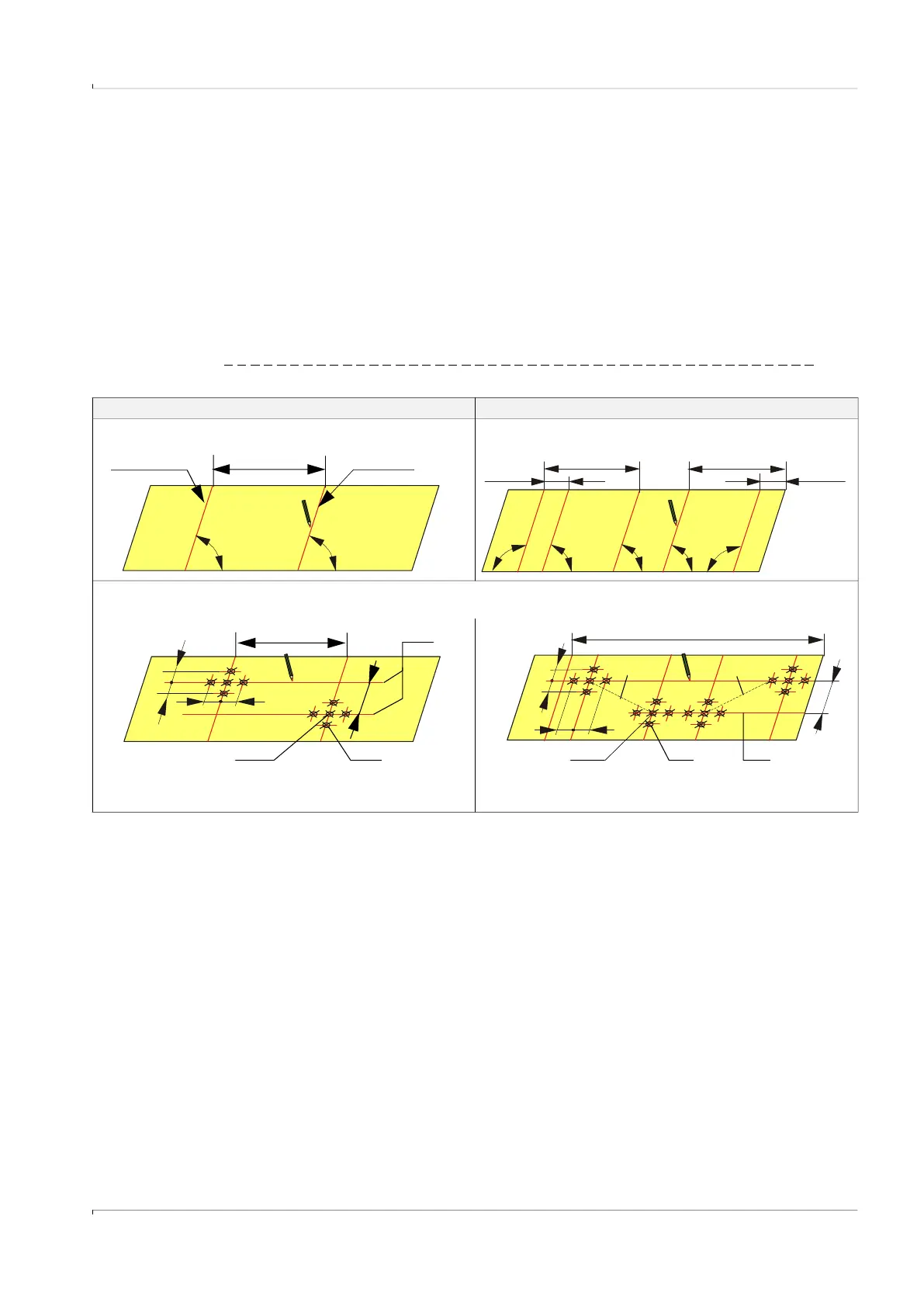
Marking the nozzle positions on the pipeline
Fig. 19 Determining the nozzle positions on the strip
1-path measurement 2-path measurement
5) Draw guide lines (1) for the nozzle positions with the previously calculated nozzle offset a, mark crossing points (2) and draw marking
points (3) in distance 60 mm (x) from the crossing points.
Overlap line U/2 Kink line
90 ° 90 °
4a) Roll the strip out again and mark the kink line.
90 ° 90 ° 90 ° 90 ° 90 °
4b) Roll the strip out again and mark the lines as follows:
2.498•r 2.498•r
0.6435•r 0.6435•r
r = D/2
x
x
x x
U / 2
a
2 3
x
x
x x
a
U
1
2 3
Path 1 Path 2
 Loading...


