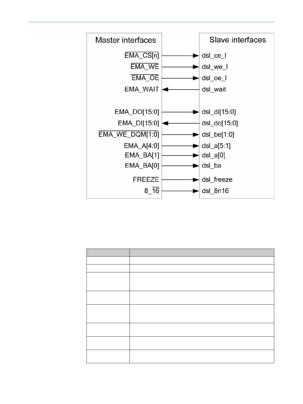
Figure 39: Allocation of parallel interface block to host
The table below provides details of the interface installation:
Table 193: Details of the parallel interface blocks
Interfaces signal Installation detail
dsl_di, dsl_do 16 bit wide data bus with separate input and output direction.
dsl_a Address bus for addressing 16 bit registers.
dsl_ba Sub-address for 8 bit interface. If the parallel bus is used with a 16 bit
wide EMIFA interface, only even addresses are used and this input is not
used.
dsl_be_l "Switch on single byte" inputs. These inputs are used to access individual
bytes of a 16 bit wide EMIFA interface.
dsl_ce_l Slave parallel bus selection. This signal can be an internally generated
selection signal (chip enable) or part of the address decoding. If this sig‐
nal is deactivated ('1'), no access to the DSL Master is possible.
dsl_oe_l Input "Output switch on". This signal gives the time control for a direction
switch of the bi-directional bus.
dsl_we_l Input "Switch on write access". This signal gives the time control for a
write access to the DSL Master.
dsl_wait Waiting time Host direction The minimum requirement for the bus states
of the parallel bus are specified in Table 9.
In addition to the EMIFA signals, the dsl_freeze and dsl_8n16 signals are imple‐
mented.
FPGA IP-CORE
9
8017595/ZTW6/2018-01-15 | SICK T E C H N I C A L I N F O R M A T I O N | HIPERFACE DSL
®
147
Subject to change without notice