The bit is described according to the following example: "Function" "Reset value", e.g.
"R/W-0"
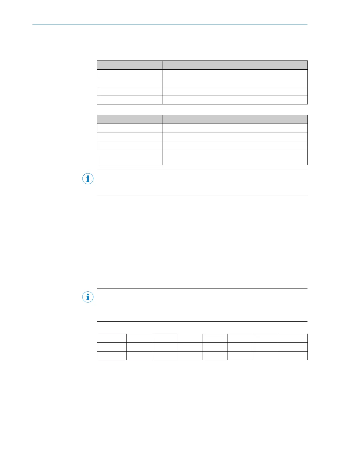
Table 16: Function symbols for bits
Function symbol Meaning
R Bit can be read.
W Bit can be set and deleted.
C Bit can only be deleted.
X Bit is not installed and will always be read as "0".
Table 17: Symbols for bit reset values
Reset value Meaning
0 The bit is deleted after a reset.
1 The bit is set after a reset.
x After a reset, the bit has no defined value.
- In the register diagram:
The bit is not installed and will always be read as "0".
NOTE
It should be noted that read access to a bit that can only be written ("W") always returns
the value "0". If a register address that is not used is read, the result will be “0” as well.
6.2 Online Status D
The Online Status D is a non-storing copy of registers EVENT_H and EVENT_L. The sta‐
tic information in these registers must be deleted by the user after the read process, by
writing the value "0" to the corresponding bit in the register, whilst the Online Status D
only shows the current status without storing previous indications. The signal name of
the Online Status is online_status_d (with d indicating drive).
online_status_d is given in two bytes. If an SPI block is used for interfacing the IP
Core, online_status_d is transmitted in each transaction in the first two bytes via
the spi_miso output. When a parallel bus interface is used for drive interface,
online_status_d has 16 dedicated output signals available.
NOTE
It should be noted that when the parallel bus interface is used the 16 signals of the
Online Status D are not frozen during a read access. If required, the user can insert a
Latch (e.g. using the hostd_fcode.inlinesignal).
Table 18: Online Status D, High Byte
R-0 R-0 R-1 R-1 R-1 R-1 R-1 R-1
INT SUM SCE FIX1 POS VPOS DTE PRST
Bit 7 Bit 0
Bit 7
INT: Status of the Interrupt output
This bit represents an exception to the Online Status D, as this bit does not relate to an
event indication. INT provides the value of the physical INT output so that request man‐
agement (polling) can be established. The importance of this flag depends on the Inter‐
rupt sources monitored.
1 = interrupt output on "High" level
0 = interrupt output on "Low" level
6
REGISTER MAP
30
T E C H N I C A L I N F O R M A T I O N | HIPERFACE DSL
®
8017595/ZTW6/2018-01-15 | SICK
Subject to change without notice