sync
cycle
dsl_out
DSL Frame DSL Frame DSL Frame DSL Frame DSL Frame DSL Frame
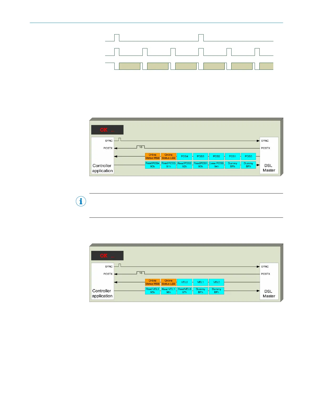
Figure 21: SYNC mode signals
The arrival of a requested fast position is indicated by the POSTX Online Status bits of
drive interface (see chapter 6.2).
The position value can be polled via drive interface from the POS0 to POS4 registers of
the DSL Master (see chapter 6.3.12).
Figure 22: Polling registers for the fast position in SYNC mode
NOTE
It should be noted that polling of fewer than the five full position registers may be
appropriate dependent upon the application. This enables fast reading of the position.
The rotation speed of the motor feedback system can be read in the same way. The
rotation speed is also measured and transmitted synchronously with the sync signal.
This is explained in figure 23.
Figure 23: Polling of rotation speed registers in SYNC mode
7.4
Safe position, Channel 1
The motor feedback system safe position is transmitted as a complete absolute posi‐
tion. This makes internal validation of the data transfer possible.
The complete transmission is available every eighth protocol frame. Therefore the posi‐
tion values are older than the fast position values received in the same frame.
7 CENTRAL FUNCTIONS
66
T E C H N I C A L I N F O R M A T I O N | HIPERFACE DSL
®
8017595/ZTW6/2018-01-15 | SICK
Subject to change without notice
 Loading...


