6 Register map
The DSL Master is accessible via register in three different register blocks. Each register
block has its own address area (see table 15).
Table 15: Register blocks address area
Register block Address area Functions
Drive 00h to 3Fh
60h to 6Fh
Process data Channel, position/status
Parameters Channel (long messages)
SensorHub Channel
Safe 1 00h to 7Fh Safe Channel 1, position/status
Parameters Channel (short messages)
Safe 2 00h to 3Fh Safe Channel 2, position/status
All IP Core registers and functions can be accessed via drive interface. As an option, the
SensorHub Channel data is accessible via the SPI PIPE interface.
In addition, the DSL Slave interface registers are mirrored as decentralized registers.
The address area 40h to 7Fh is intended for this. The addressing of these registers is
identical to the addressing of the registers in the DSL Master. The answer to the trans‐
action is, however, delayed and must be read individually (see under "Short message",
in chapter 7.5.1).
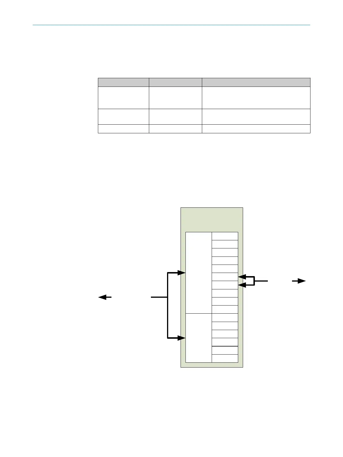
figure 13 below shows via which interface a connection to which register block is estab‐
lished.
DSL Master Primary
functions
Registers
for all
main
functions
00h
01h
|
|
2Dh
2Eh
|
3Eh
3Fh
Drive interfacexx
SPI-PIPEx
DSL
Slave
Remote
Registers
40h
41h
|
|
|
7Eh
7Fh
(optional)
Figure 13: Register block overview
6.1
Explanation of the registers
In the following description of the registers, symbols are used to describe the standard
value of a bit following a reset. Additional symbols are used to describe the functions
provided to the frequency inverter application for this bit.
REGISTER MAP 6
8017595/ZTW6/2018-01-15 | SICK T E C H N I C A L I N F O R M A T I O N | HIPERFACE DSL
®
29
Subject to change without notice
 Loading...


