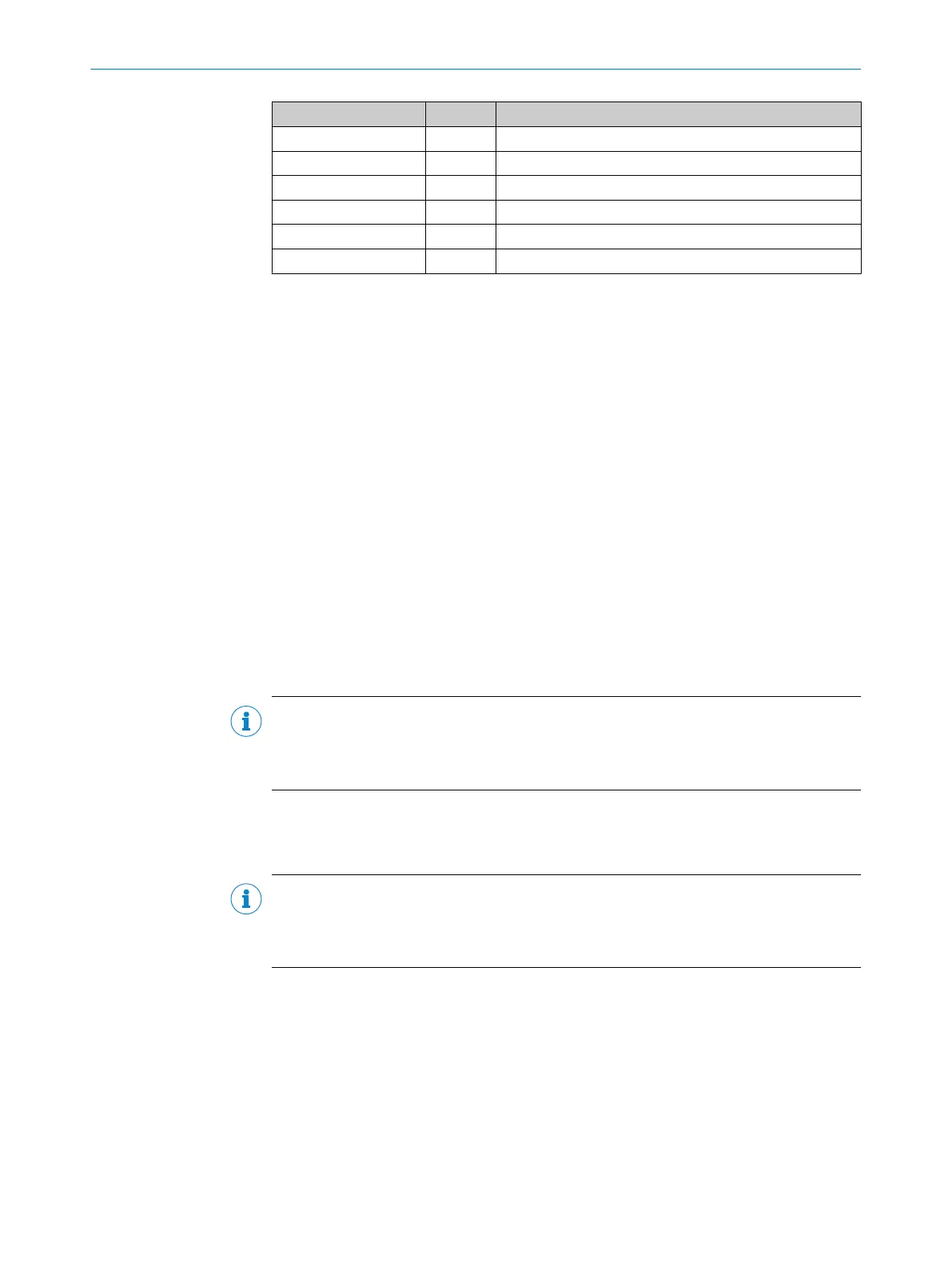
Pin name Type Function
hostd_a(0:6) Input Register address bus
hostd_di(0:7) Input Register input data bus
hostd_do(0:7) Output Register output data bus
hostd_r Input Read signal
hostd_w Input Write signal
hostd_f Input Freeze signal
Example installations of interface blocks for the Drive interface of the DSL Master are
supplied together with the IP Core. These examples include a serial SPI interface and a
parallel Texas Instruments EMIFA interface. For more information please see
chapter 9.1.
5.2 SPI PIPE Interface
The SPI PIPE is a read-only Serial Peripheral Interface (SPI). SPI PIPE is an optional com‐
munication channel between the frequency inverter application and the DSL Master IP
Core. Read processes on the SensorHub Channel can be carried out via this interface.
Alternatively, this data can also be read from the registers by standard transactions via
Drive interface.
The type of access to the SensorHub Channel is selected by setting or deleting the
SPPE bits in the SYS_CTRL register (see chapter 6.3.1). If the SPPE bit is deleted, the
data and the status of the SensorHub channel are accessible via the DSL Master
PIPE_S (2Dh) and PIPE_D (2Eh) registers. If the SPPE bit is set, the SensorHub Channel
is read using the SPI PIPE "Read Pipeline" transaction.
SPI PIPE should be activated if, at a fast frequency inverter cycle, the bandwidth of
Drive interface is insufficient to access position and pipeline data, or if the pipeline
data is being processed by another frequency inverter application resource.
NOTE
It should be noted that in every case, the configuration of external sensor components
at the sHub
®
is carried out via the DSL Master Parameters Channel. The SPI PIPE pro‐
vides only one read access to the SensorHub Channel (see chapter 3.5).
The SensorHub Channel data is kept in a FIFO (First In First Out) buffer that can hold 8
bytes. In addition, for each data byte, status information is also stored in the FIFO buffer
(see chapter 6.3.22 and chapter 6.3.23).
NOTE
It should be noted that the FIFO buffer can only store 8 bytes of SensorHub Channel
data. If the buffer is not read quickly enough, old data will be overwritten. This is indi‐
cated by a flag in the FIFO buffer status information.
The SPI Master for the SPI PIPE is the frequency inverter application. The SPI functions
"Slave Selection" (Pin: spipipe_ss) and "clock" (Pin: spipipe_clk) are controlled by
the frequency inverter application. The SPI function "Data, Master input Slave output"
(Pin: spipipe_miso) is controlled by the DSL Master.
SPI PIPE has the following SPI characteristics:
•
PHA = 1 (Sampling for clock trailing edge, data changes for clock leading edge)
•
POL = 0 (Basic clock value)
The data with the highest value bit (MSB) is given first.
INTERFACES
5
8017595/ZTW6/2018-01-15 | SICK T E C H N I C A L I N F O R M A T I O N | HIPERFACE DSL
®
23
Subject to change without notice