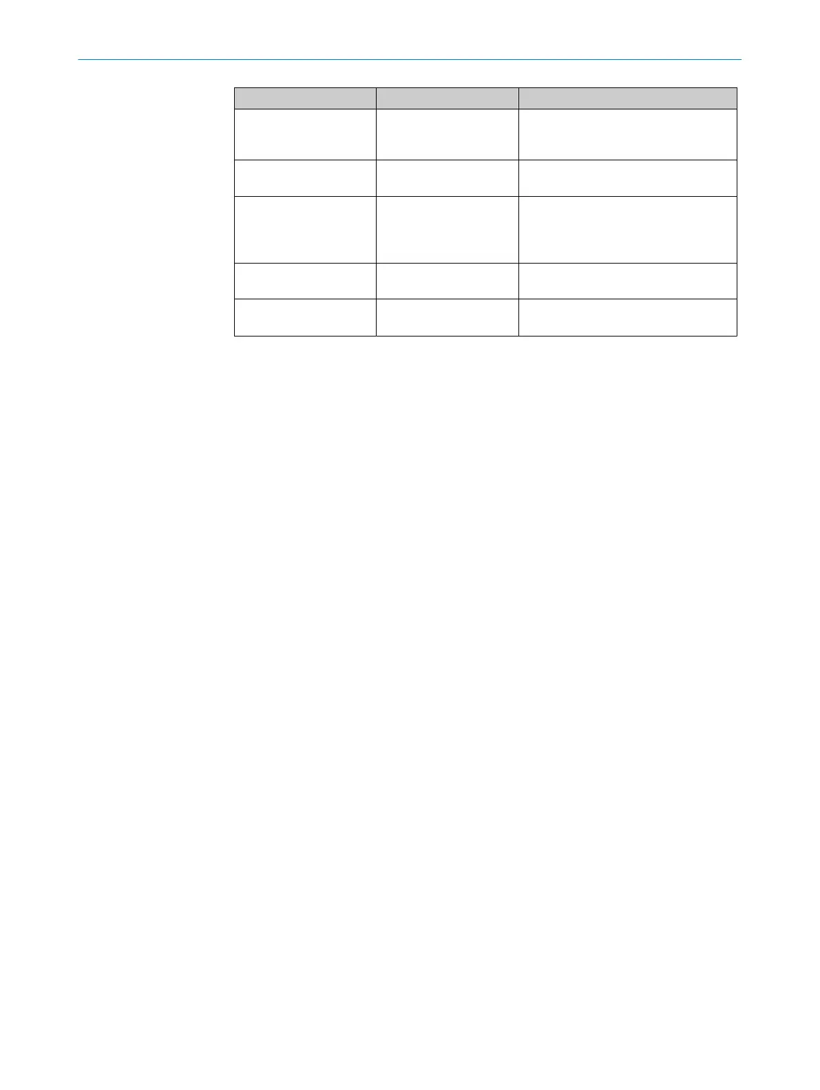
Status Prerequisite Indication
Synchronization error Time overrun (typ. after 5
ms) during the DSL syn‐
chronization
LINK = 0
(MASTER_QM register)
Free running mode Successful
DSL synchronization
LINK = 1
(MASTER_QM register)
SYNC mode ES > 0
(SYNC_CTRL register),
Cyclic signal to SYNC
input
Synchronous encoder position in the
POS0 to POS4 registers
Invalid position External transmission or
encoder error
Error bit set in EVENT_H, EVENT_L or in
Online Status
Protocol reset Two successive transmis‐
sion errors
PRST = 1
(EVENT_H register or Online Status)
7.2 System diagnostics
HIPERFACE DSL
®
provides comprehensive system diagnostics in relation to communi‐
cations quality both during the development of a DSL system as well as during normal
operation.
7.2.1 System diagnostics during development
During the development of a DSL system, several registers are involved in the diagnos‐
tics of correct use and operation. These include:
•
Quality monitoring MASTER_QM
•
Edge register EDGES
•
Run time register DELAY
After the DSL connection has been activated (OEN bit, see chapter 6.3.1), the LINK flag
in the MASTER_QM register must be checked for the set value "1". This indicates that
the connection to the motor feedback system was successfully established.
If this bit remains deleted for longer than the expected start-up time (see encoder
datasheet), there is a fundamental problem in the connection between the frequency
inverter and the motor feedback system.
Check whether the encoder is supplied with power.
Using an oscilloscope, also check whether any level changes in the transmission fre‐
quency range can be identified over the data cables between the frequency inverter
and the encoder.
Using the run time register (see chapter 6.3.8), it is possible to identify whether the DSL
signal cable delay complies with the specification. The run time is mainly a result of the
length of the cable between the frequency inverter and the motor
feedback system. In addition, the selection of the interface drive (RS485 transceiver)
has an effect on the signal run time.
The value of the EDGES register (see chapter 6.3.7) indicates how well or badly the DSL
Master can sample the communication signal coming from the motor feedback system.
Start the check of the bit sampling pattern with the motor switched off. If several bits
have been set in the sampling pattern (more than four), the encoder shielding design
should be checked. The aim should be that, during interference-free operation, the min‐
imum number of bits is set in the sampling pattern.
7
CENTRAL FUNCTIONS
60
T E C H N I C A L I N F O R M A T I O N | HIPERFACE DSL
®
8017595/ZTW6/2018-01-15 | SICK
Subject to change without notice