Bit 7 Bit 0
Bit 7-0 Bit sampling pattern: Identification of edges in the cable signal
1 = An edge was detected in the time period of the corresponding bit.
0 = No edge was detected in the time period of the corresponding bit.
6.3.8 Delay / RSSI
The DELAY run time register stores information about the run time delay of the system
cable and the signal strength. The register can be used to monitor the connection qual‐
ity.
The register is write protected.
Register 0Ah: Run time delay
R-0 R-0 R-0 R-0 R-0 R-0 R-0 R-0
RSSI Cable delay
Bit 7 Bit 0
Bit 7-4 RSSI: Indication of the received signal strength
4 bit value for the cable signal strength, from "0" to "12". Higher values indicate better
connection quality. Low connection (<2) quality affects QM.
RSSI is continuously updated during operation and used for signal monitoring during
run time.
Bit 3-0 Cable delay:
4 bit value for cable delay. This value gives the cable signal round trip delay of cable
and transceivers in bits. This value enables a rough estimate of cable length to be
made.
The value for Line Delay does not change after the start-up phase. A fresh value for
Line Delay is only measured after a forced reset of the protocol.
table 22 below shows the relationship between the value in Line Delay and the cable
length of the DSL connection.
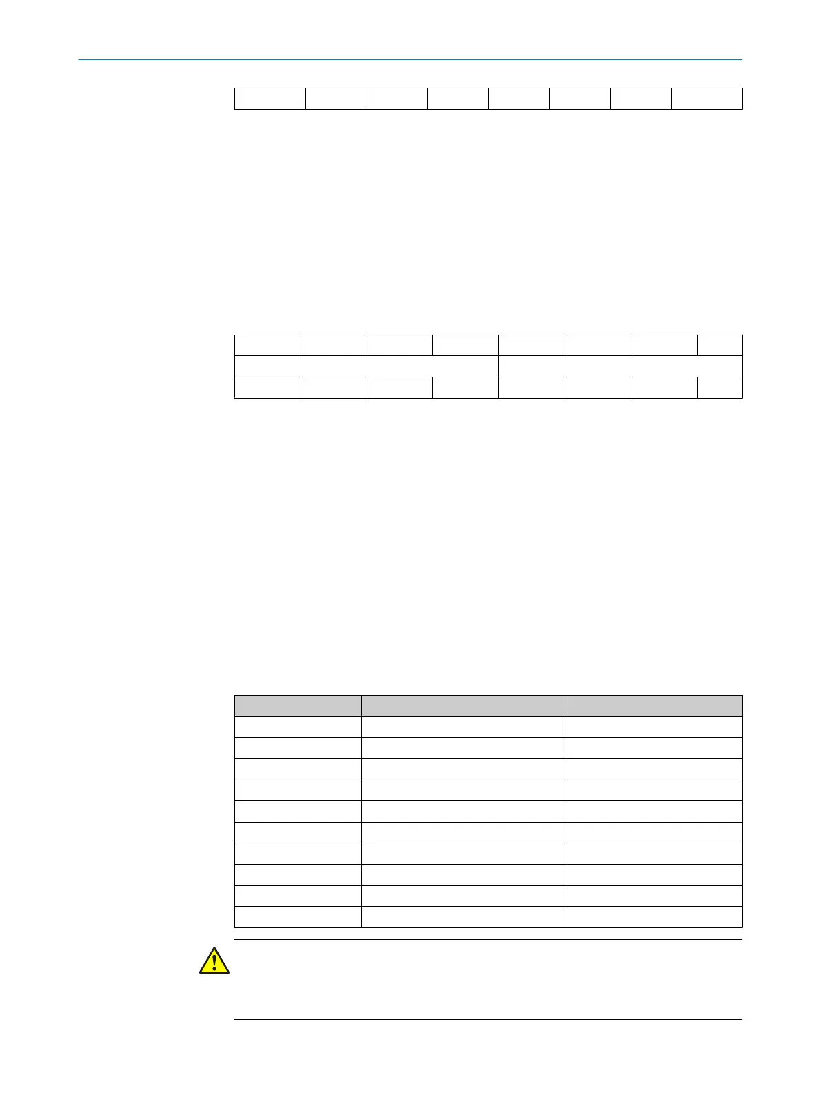
Table 22: Cable delay
Cable delay DSL connection cable delay Cable length DSL connection
0 <100 ns < 10 m
1 100 to 200 ns 10 to 20 m
2 200 to 300 ns 20 to 30 m
3 300 to 400 ns 30 to 40 m
4 400 to 500 ns 40 to 50 m
5 500 to 600 ns 50 to 60 m
6 600 to 700 ns 60 to 70 m
7 700 to 800 ns 70 to 80 m
8 800 to 900 ns 80 to 90 m
9 900 to 1000 ns 90 to 100 m
CAUTION
A value above "9" indicates a delay of greater than 1 µs. Such a value will lead to a
violation of the specification for cycle time. In this case, a check should be made of
whether the cable complies with the cable specification.
6 REGISTER MAP
42
T E C H N I C A L I N F O R M A T I O N | HIPERFACE DSL
®
8017595/ZTW6/2018-01-15 | SICK
Subject to change without notice
 Loading...


