5 Interfaces
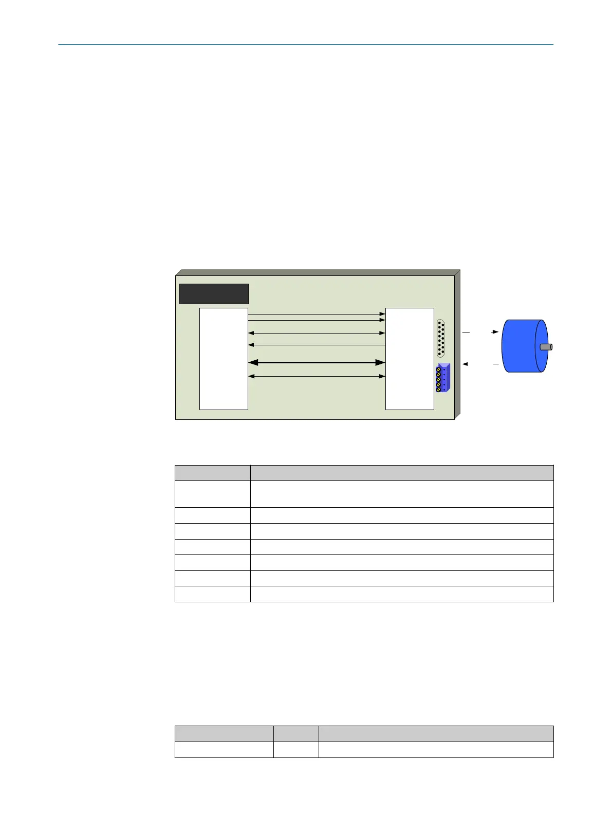
The IP Core of the DSL Master includes interfaces to the motor feedback system (DSL
Slave) and to the frequency inverter application (see figure 9).
The motor feedback system communicates via a DSL connection with the DSL Master.
All data channels between the DSL Master and DSL Slave are routed via this connec‐
tion.
The user application is connected via one interface (choice of SPI or parallel bus) and
several control signals . In addition, the frequency inverter provides a clock signal (CLK)
and a reset signal (RST) to the DSL Master IP Core. By means of these signals, a
defined start-up performance is achieved.
According to the requirements of the particular application, an optional serial interface
(SPI-PIPE) can be employed to use the SensorHub Channel (see chapter 3.5).
The various interfaces correspond to the tasks described in table 10.
Inverter
OK …
MFB
system
DSL
Response
Drive
Application
DSL
Master
DSL
Request
rst rst
clk clk
Drive interface Drive interface
SPI-PIPE SPI-PIPE
Control signals
Control signals
Test signals
Test signals
Figure 9: DSL system interfaces
Table 10: Interface functions
Interface Function
Drive interface Register-based access to all DSL Master and DSL Slave functions relevant
for the core frequency inverter application
SPI PIPE Optional register-based access to SensorHub Channel data
Control signals DSL Master indication and control signals
Test signals Test signals for development or fault-finding for a DSL controller
CLK Clock signal for the IP Core circuit
RST Reset signal for the IP Core circuit
DSL Connection to the motor feedback system
5.1 Drive interface
The drive interface forms the central communications interface between the frequency
inverter application and the DSL Master IP Core. Absolute and fast position data can
be read via this interface. The functions of the motor feedback system are also accessi‐
ble via this interface.
The following signals are used for Drive interface:
Table 11: Drive interface signals
Pin name Type Function
online_status_d(0:15) Output IP Core status (see chapter 6.2)
5 INTERFACES
22
T E C H N I C A L I N F O R M A T I O N | HIPERFACE DSL
®
8017595/ZTW6/2018-01-15 | SICK
Subject to change without notice