When accessing the SensorHub Channel via the SPI PIPE, the first four bits of the sta‐
tus buffer (0101) show a different value for each transaction, in order to check the cor‐
rect function of the interface.
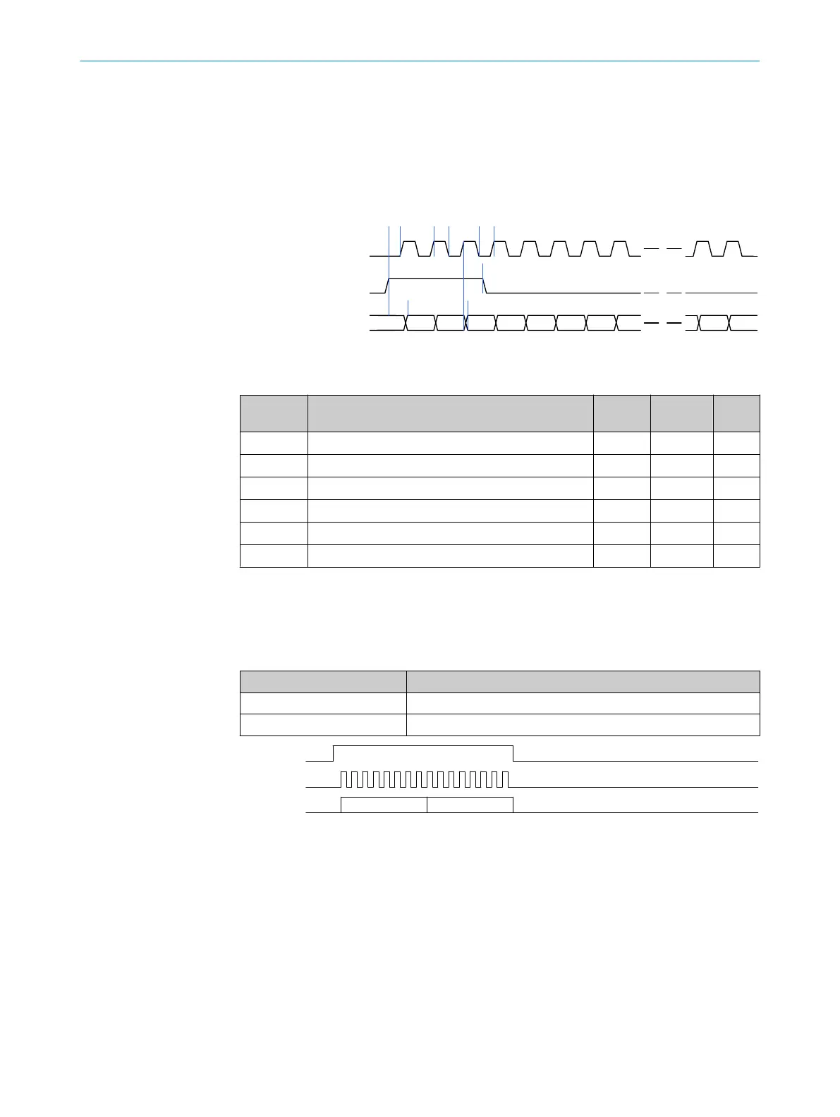
5.2.1 SPI-PIPE timing
The time sequence for SPI PIPE is shown in the time sequence diagram (figure 10 )
below and in table 12.
spipipe_clk
spipipe_miso
POL=0
PHA=1
1 2 3 4 5 6 7 8
a
b c
n-1 n
d
e
f
spipipe_ss
Figure 10: SPI-PIPE interface time control
Table 12: SPI-PIPE time control
Diagram
reference
Description Mini‐
mum
Maxi‐
mum
Units
A Assertion of spipipe_ss before spipipe_clk 30 ns
B Time for spipipe_clk high 30 ns
C Time for spipipe_clk low 30 ns
D spipipe_ss pulse width 30 ns
E Delay spipipe_miso after spipipe_ss high 25 70 ns
F Delay spipipe_miso after spipipe_clk high 25 70 ns
5.2.2 Read pipeline
The SPI PIPE transaction "Read Pipeline" is used for access to the FIFO buffer values
that contain the data and status of the SensorHub Channel.
Table 13: "Read Pipeline" transaction
Symbol Meaning
PIPE STATUS SensorHub Channel status (see chapter 6.3.21)
PIPE DATA SensorHub Channel data (see chapter 6.3.22)
spipipe_clk
spipipe_miso
PIPE STATUS PIPE DATA
spipipe_ss
Figure 11: "Read Pipeline" transaction
5.3 Control signals
Various control signals are available between the DSL Master and the frequency
inverter application to configure the performance of the IP Core or to carry out fast
monitoring of the IP Core status.
5.3.1 SYNC signal
sync is a DSL Master digital input.
5 INTERFACES
24
T E C H N I C A L I N F O R M A T I O N | HIPERFACE DSL
®
8017595/ZTW6/2018-01-15 | SICK
Subject to change without notice
 Loading...


