7 Central functions
In this chapter, access to the central sensor functionality via interfaces and registers is
described.
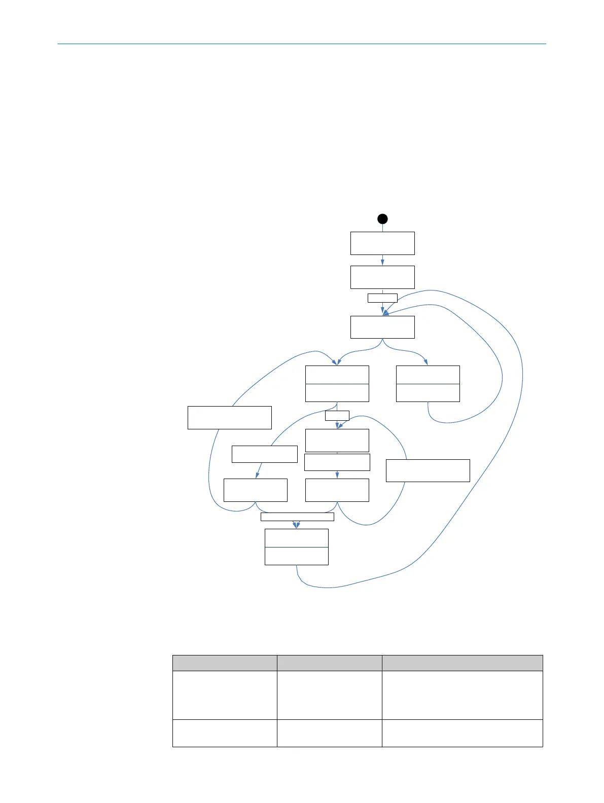
7.1 System start
As soon as the motor feedback system is supplied with power, a forced reset ensures
that a defined system start status is produced in the DSL Master IP Core.
figure 17 shows the status table for system start.
DSL Master
Start
DSL
Synchronization
Synchronization
error
LINK = 0
Free-running mode
LINK = 1
SYNC mode
Invalid positionInvalid position
Error acknowledged,
No further transmission error
Protocol reset
PRST = 1
Power on,
Reset sequence
OEN = 1
Error acknowledged,
No further transmission error
ES > 0
Transmission error,
Encoder error
Transmission error,
Encoder error
Several transmission errors
Figure 17: Status table for DSL system start.
Individual conditions are described in table 28.
Table 28: Conditions at DSL system start
Status Prerequisite Indication
DSL Master start Switching on supply volt‐
age.
Reset process (Duration:
500 ms)
Communication via drive interface is
possible
DSL synchronization OEN = 1
(SYS_CTRL register)
None
CENTRAL FUNCTIONS 7
8017595/ZTW6/2018-01-15 | SICK T E C H N I C A L I N F O R M A T I O N | HIPERFACE DSL
®
59
Subject to change without notice