1 A correct control signal must be applied at the sync input. The signal must corre‐
spond with the specifications for pulse width and cycle time.
2 Setting or deleting the SPOL bit in the SYS_CTRL register determines whether the
position measurements are to be triggered by the leading of the trailing edge of
the control signal. The set latency of the DSL system is measured from this edge.
3 The correct ES divider must be set in the SYNC_CTRL register. This divider deter‐
mines how many position samplings and transmissions will be undertaken for
each control signal. Do not change setting of ES divider during start up or opera‐
tion.
CAUTION
The ES divider must be selected so that the cycle time between the two position sam‐
plings corresponds to the prescribed range limits (package cycle time) in see table 1.
The range limits for the ES divider can be calculated as follows:
ES ≤ t
Sync
/ t
Min
ES ≥ t
Sync
/ t
Max
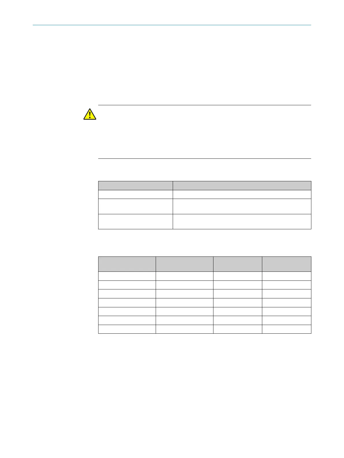
The symbols used in the formulae are explained as follows:
Table 31: Symbols used in the formulae
Symbol Description
tSync Cycle time of the pulse signal at the SYNC input
tMin Minimum cycle time for the transmission of DSL frames
(11.95 µs)
tMax Maximum cycle time for the transmission of DSL frames
(27,00 µs)
table 32 below contains typical cycle times for the control signal and the valid ranges of
ES divider values.
Table 32: Cycle times for SYNC signals and valid ES values
Frequency of the SYNC
signal (kHz)
Cycle time of the SYNC
signal (µs)
Minimum value ES Maximum value ES
2 500 19 41
4 250 10 20
6.25 160 6 13
8 125 5 10
16 62.5 3 5
40 25 1 2
38 to 82 26.3 to 12.2 1 1
After the sequence described above, SYNC mode is activated. In the specified "start-up
time” the protocol is synchronized with the applied sync signal. Following this period,
the position value is available with constant latency after the data package has been
transmitted (see figure 21).
The time profile of the relevant signals in SYNC mode is shown in the following graphic.
This shows the sync signal, the cycle signal generated from the ES divider and the
dsl_out DSL output signal.
CENTRAL FUNCTIONS
7
8017595/ZTW6/2018-01-15 | SICK T E C H N I C A L I N F O R M A T I O N | HIPERFACE DSL
®
65
Subject to change without notice