There are three ways to synchronize the internal time of the device with the system
time of the controller:
•
Via telegram: The computer queries the internal time of the device using a tele‐
gram. The device writes its internal time in a telegram and sends this to the
computer. Sending can happen with a delay time of up to a few milliseconds,
which results in some uncertainty.
•
Via Timer Read telegram: The computer retrieves the internal time of the device
using a telegram. The hardware output provides a pulse of at least 10ms once
the internal time stamp is written in the telegram. If the telegram is then received
by the computer, this can add the delta between the pulse and receipt to the time
entered in the telegram. As a result, the external computer can determine the
actual time in the device.
•
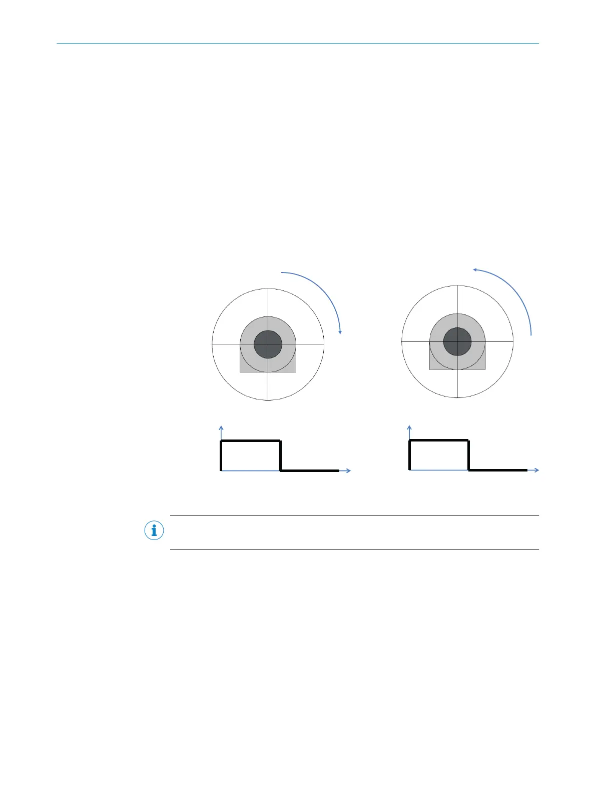
Via index (pulse at hardware output): The device outputs a signal depending on
the scanner head position. . This signal is used, for example, to synchronize scans
with the position of a swivel device for 3D measurement.
270°
180°
0°
90°
180°
0°
90°
270°
(-90°)
GND
+ 24VDC
0°
180°
360°
GND
+ 24VDC
270°
90°
270°
LD-LRS 36x1 LD-LRS 36x0
Figure 14: Pulse at the head position
NOTE
Program the controller to respond to the leading edge of the output pulse.
3.4.11.5 Distance between the device and the object/surface to be measured
The laser beam expands with increasing distance from the device.
With recessed installation of the device, it is important to consider how the laser beam
expands as the distance increases in order to avoid incorrect measurements. If the
device is mounted in an unfavorable position, depending on the distance, this could
therefore mean that objects in the scanning area are detected constantly as they are
hit by the laser beam.
3 PRODUCT DESCRIPTION
22
O P E R A T I N G I N S T R U C T I O N S | LD-LRS 8016506/1G07/2020-11-08 | SICK
Subject to change without notice