OPERATING INSTRUCTIONS | LFP INOX 8019921/15H0 / 2019-09-30 | SICK AG
Irrtümer und Änderungen vorbehalten
16
5 MOUNTING
hygienic design, e.g. surface roughnesses of parts that come into contact with media
Ra ≤ 0.8 μm.
Note:
The distances are the same for sensors with remote amplier.
The drainability of the tank and coupling must not be hindered by installation of the
measurement probe.
When installing the measurement probe in a coupling, it must be ensured that the
distance between the probe and coupling wall is greater than the length of the coupling
(maximum length L <= (D-d))
In the case of installation in a tank, it must be ensured that the cleaning tting is posi-
tioned in such a way that both the connection and the sensor can be completely wetted
and cleaned.
When using hygienic process adapters, the notes “17 Accessories” are to be observed
(insert note).
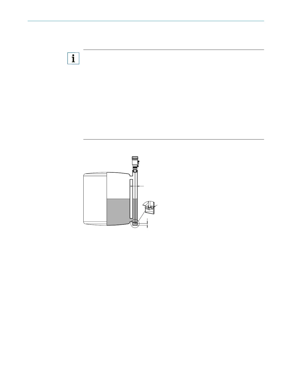
5.1.2 Installation in a metal immersion tube or metal bypass
D
B
Fig. 3: LFP Inox
1 Centering
2 LFP Inox
D ≥ DN 40
Distance bypass oor / container oor
B ≥ 15 mm
Centering: To prevent contact between the probe and the bypass pipe during oscilla-
tions, the probe should be centered according to its length and depending on the diam-
eter of the bypass pipe. To do this, it is necessary to insert one or two centering pieces,
see “17 Accessories”.
Tank welds can aect the measurement accuracy.