OPERATING INSTRUCTIONS | LFP INOX 8019921/15H0 / 2019-09-30| SICK AG
Irrtümer und Änderungen vorbehalten
19
6ELECTRICAL INSTALLATION
6.2 Electrical connection
6.2.1 Overview of the electrical connections
The sensor is connected using a pre-assembled female cable connector with 1 x M12
plug connector (5-pin or 8-pin). With the power switched o, plug the female cable con-
nector into the sensor and screw it tight.
Connect the cable according to its function. After the supply voltage has been applied,
the sensor carries out a self-test. Once installed, the sensor is ready for operation on
completion of the self-test (< 5 s) and the display shows the current measured value.
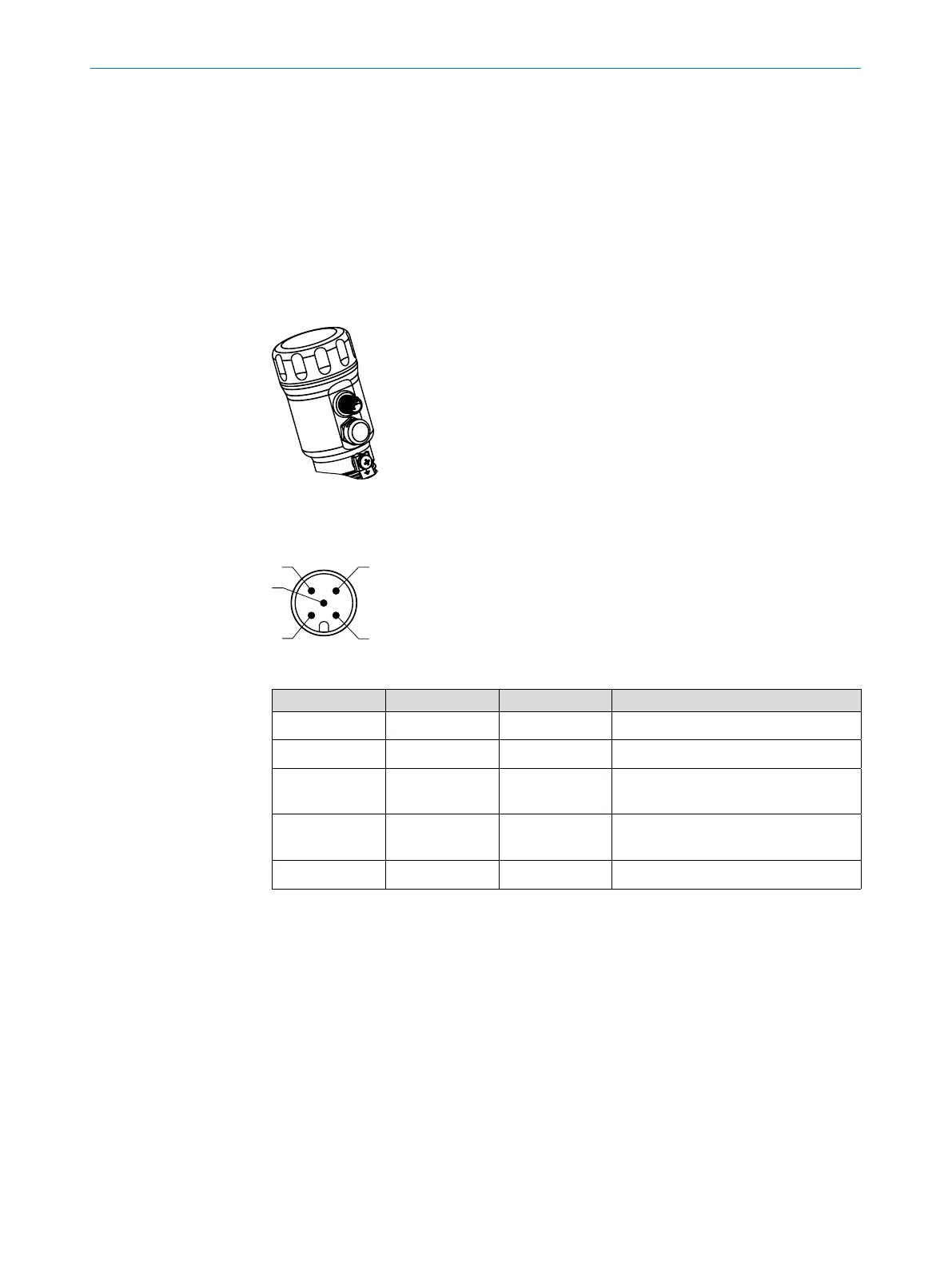
Fig. 4: LFP Inox
6.2.2 Pin assignment, M12 plug connector, 5-pin
Fig. 5: M12 x 1 plug connector, 5-pin
Contact Marking Wire color Description
1 L+ Brown Supply voltage
2 Q
A
White Analog current / voltage output
3 M Blue Ground, reference potential for cur-
rent / voltage output
4 C/ Q
1
Black Switching output 1, PNP / IO-Link
communication
5 Q
2
Gray Switching output 2, PNP / NPN