OPERATING INSTRUCTIONS | LFP INOX 8019921/15H0 / 2019-09-30 | SICK AG
Irrtümer und Änderungen vorbehalten
56
14 TECHNICAL DATA
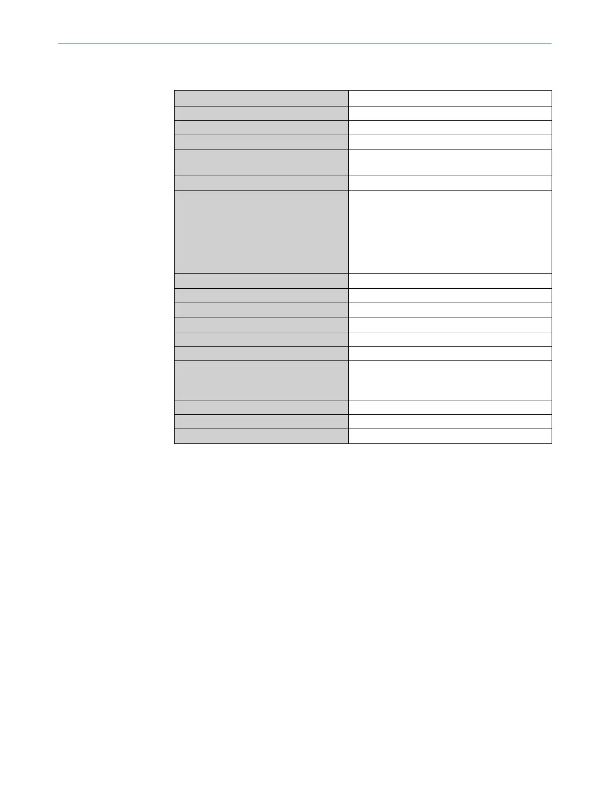
14.6 Electrical connections
Supply voltage 12 V DC ... 30 V DC
Current consumption ≤ 100 mA at 24 V without output load
Initialization time ≤ 5 s
Protection class III
Connection type M12 x 1 (5-pin)
M12 x 1 (8-pin)
Hysteresis Min. 3 mm, freely congurable
Output signal
1)
4 mA to 20 mA / 0 V to 10 V automatically switch-
able depending on output load
1)
1 PNP transistor output (Q1) and 1 PNP/NPN
transistor output (Q2) switchable, or
1 PNP transistor output (Q1) and 3 PNP/NPN
transistor outputs (Q2 to Q4) switchable (depend-
ing on type)
Signal voltage HIGH Uv –2 V
Signal voltage LOW ≤ 2 V
Output current < 100 mA
Inductive load < 1 H
Capacitive load 100 nF
Temperature drift < 0.1 mm/K
Output load 4 mA ... 20 mA < 500 ohms at Uv > 15 V
4 mA ... 20 mA < 350 ohms at Uv > 12 V
0 V ... +10 V > 750 ohms at Uv ≥ 14 V
Lower signal level 3.8 mA ... 4 mA
Upper signal level 20 mA ... 20.5 mA
EMC EN 61326-2-3, 2014/30/EU
1)
All connections are reverse polarity protected. All outputs are overload and short-circuit
protected.
2)
Use an energy-limited circuit for power supply as per UL61010-1 3rd Ed., Section 9.3