OPERATING INSTRUCTIONS | LFP INOX 8019921/15H0 / 2019-09-30 | SICK AG
Irrtümer und Änderungen vorbehalten
20
6 ELECTRICAL INSTALLATION
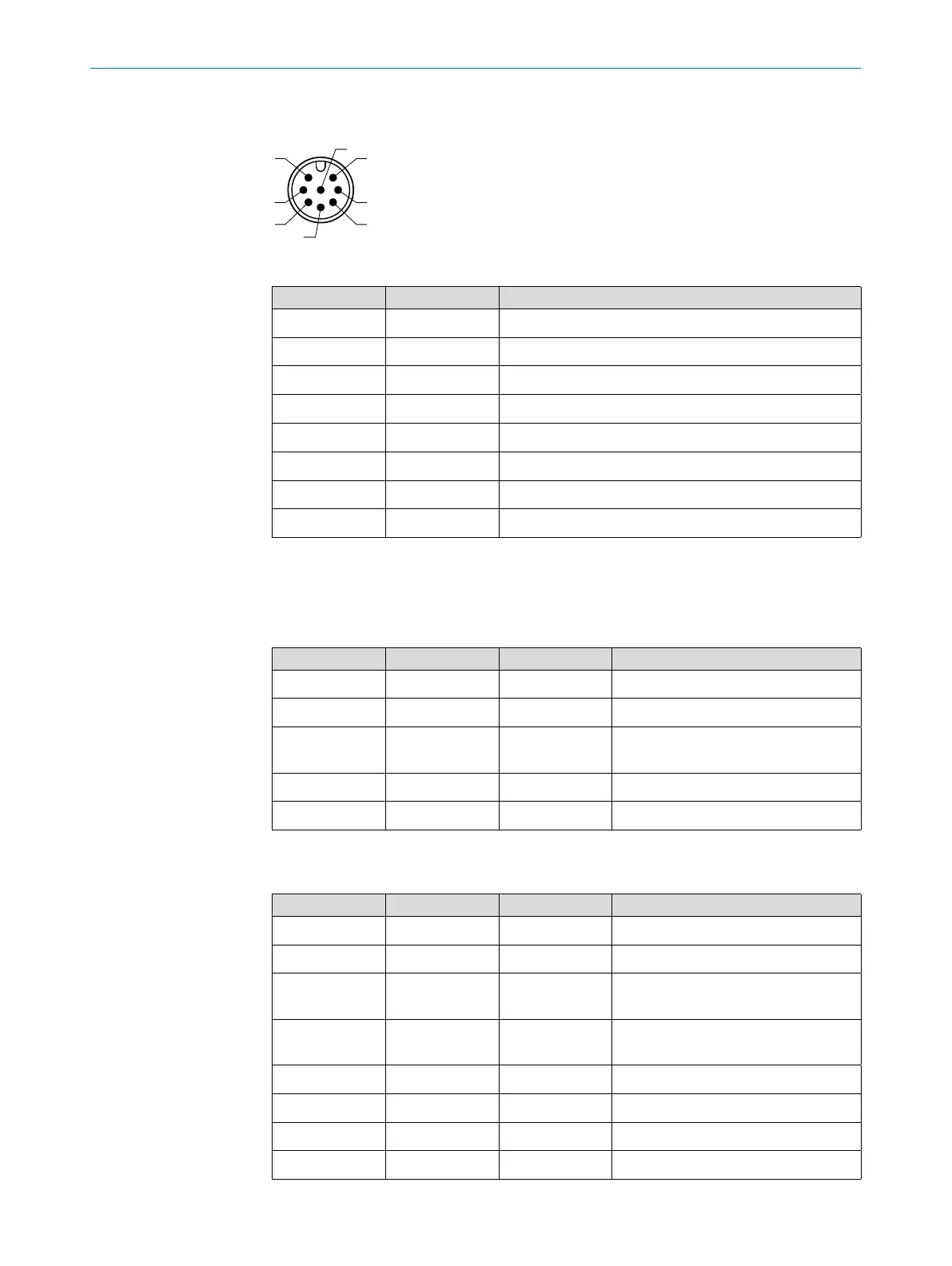
6.2.3 Pin assignment, M12 plug connector, 8-pin
2
3
4
1
7
6
Fig. 6: M12 x 1 plug connector, 8-pin
Contact Marking Description
1 L+ Supply voltage
2 Q
2
Switching output 2, PNP / NPN
3 M Ground, reference potential for current / voltage output
4 C/Q
1
Switching output 1, PNP / IO-Link
5 Q
3
Switching output 3, PNP / NPN
6 Q
4
Switching output 4, PNP / NPN
7 Q
A
Analog current / voltage output
8 No function
The wire colors for 8-pin cables are not uniform. Always note the pin assignment of the
sensor.
6.2.4 Pin assignment, cable variant, 5-pin
Contact Marking Wire color Description
1 L+ Brown Supply voltage
2 Q
A
White Analog current / voltage output
3 M Blue Ground, reference potential for cur-
rent / voltage output
4 Q
1
Black Switching output 1, PNP
5 Q
2
Gray Switching output 2, PNP / NPN
6.2.5 Pin assignment, cable variant, 8-pin
Contact Marking Wire color Description
1 L+ White Supply voltage
2 Q
2
Brown Switching output 2, PNP / NPN
3 M Green Ground, reference potential for cur-
rent / voltage output
4 C/Q
1
Yellow Switching output 1, PNP / IO-Link
communication
5 Q
3
Gray Switching output 3, PNP / NPN
6 Q
4
Pink Switching output 4, PNP / NPN
7 Q
A
Blue Analog current / voltage output
8 Red No function