OPERATING INSTRUCTIONS | LFP INOX 8019921/15H0 / 2019-09-30 | SICK AG
Irrtümer und Änderungen vorbehalten
46
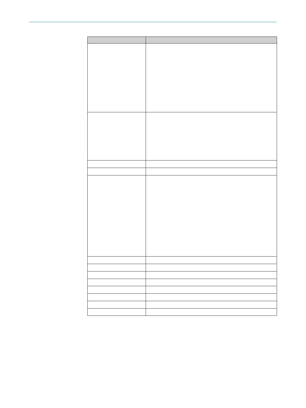
10 OVERVIEW OF PARAMETERS
Parameter Description
QATYP Output signal settings
• 4 mA ... 20 mA
• 0 V ... +10 V
• Auto V = Qa operated with voltage output of 0 V ... +10 V
• Auto A = Qa operated with current output of
4 mA ... 20 mA
• Auto? = Automatic signal detection based on the exist-
ing load resistance
During a menu query, either 4 mA ... 20 mA or
0 V ... +10 V is displayed.
QAFAIL Output behavior as per NE43 in the event of a fault (func-
tion only available when current output has been selected
under QATYP).
• 3.5 mA = Analog current output is set to 3.5 mA in the
event of a fault.
• 21.5 mA = Analog current output is set to 21.5 mA in
the event of a fault.
SimCur See “8.4.6 Testing the conguration”.
SimVol See “8.4.6 Testing the conguration”.
DspVal Display settings
• Distan = The display shows the distance in mm in rela-
tion to the end of the probe.
• QaPerc = The display shows the ll level in % in relation
to the QA analog output with the corresponding QAHIGH
and QALOW thresholds.
• QaBarG = The display shows a bar graph in relation to
the QA analog output with the corresponding QAHIGH
and QALOW thresholds.
• QaSign = The display shows the current QA output value
in mA or V.
• QxSign = The display shows the output states.
Filter See “8.4.2 Filtering measured values”.
SimLev See “8.4.6 Testing the conguration”.
RstFac Reset the set parameters to the factory settings.
EXPRT See “8.4.1 Expert mode”.
Lock See “8.4.11 Activating the display lock”.
Unit See “8.4.12 Selecting the display unit (millimeter / inch)”.
Oset See “8.4.13 Setting the oset”.
Mode See “8.4.5 Selecting evaluation process”.