Table 4: Example: Median for scan 2 and angle 4 (3 x 3 matrix: scan 1 to 3, angle 3 to 5)
Angle (distance values)
Scan 1 2 3 4 5 …
1 0 0 850 1100 1150 …
2 0 0 950 1200 1250 …
3 0 0 850 1150 1200 …
… … … … … … …
Median calculation: 850 (lowest value) | 850 | 950 | 1,100 | 1150 (median) | 1,150
| 1,200 | 1,200 | 1,250 (highest value)
3.5.8.6 Ground reference evaluation
NOTE
When the ground reference evaluation function is activated, the mean filter is automati‐
cally deactivated.
The ground reference evaluation function enables the LiDAR sensor to protect hazard‐
ous areas when used in conjunction with automated guided vehicle systems (AGVS).
Any objects lying on the path (pallets or small load carriers), or steps and depressions
in the ground, are distinguished and detected, thereby avoiding collisions.
The PC software SOPAS ET is used to configure the device and enter the installation
location (position of the device), "Operation with SOPAS ET", page 43. The following
application parameters must be taken into consideration and adhered to:
Table 5: Application parameters for ground reference evaluation
Condition Value
Mounting height 0.3 … 1.3 m
Tilt angle +11° … +30°
Overhead mounting
1
: -10° … -30°
Details see table 6, page 23
Roll angle ± 0.5°
Yaw angle Flexible
Required accuracy for the
configuration data inputs
Mounting height: ± 5 cm
Tilt angle: ± 0.5°
Ambient conditions Indoor applications, level floor surface, no slope, min. corridor
width 2 m
1
the following offset values must be configured for overhead mounting: yaw angle 180°, tilt angle 180°
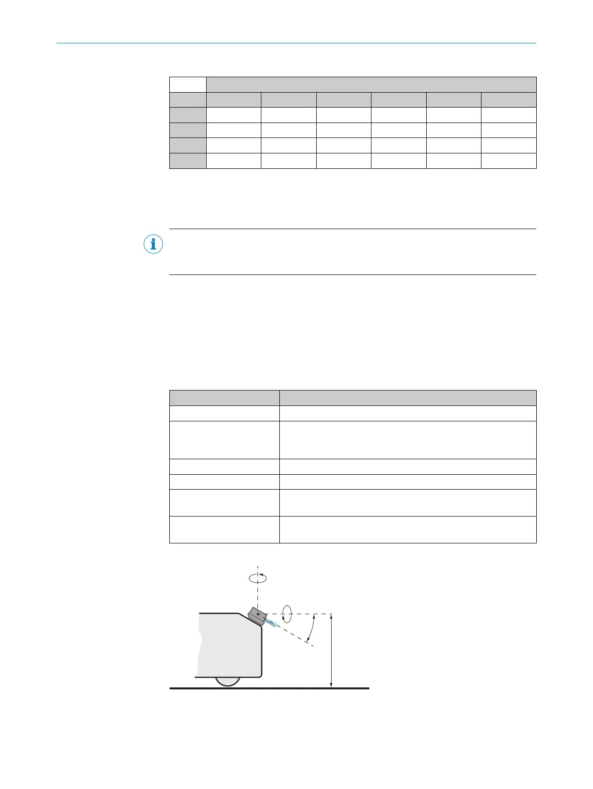
Figure 26: Ground reference evaluation, explanation of application parameters
1
Yaw angle
2
Roll angle
3 PRODUCT DESCRIPTION
22
O P E R A T I N G I N S T R U C T I O N S | MRS1000 8020494/1AZF/2021-05-10 | SICK
Subject to change without notice