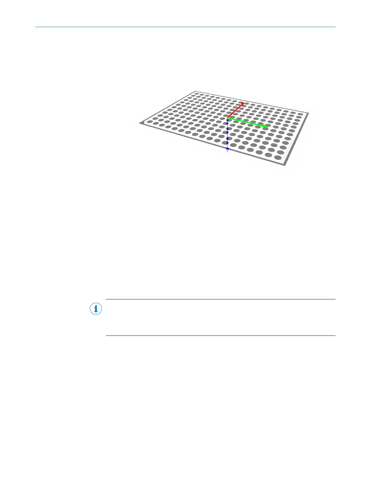
10. Define the robot work plane by jogging the robot to the alignment target points
indicated by the arrows (x-axis in red, y-axis in green, z-axis in blue) in figure 18
Figure 18: Work plane alignment base
Results
When the sensor is aligned to the work plane, an image of the alignment target is
displayed in the image window. The displayed image is rectified, that is, projected onto
the defined work plane. A blue circle, representing the position and the direction of the
alignment target, is displayed on top.
The aligned sensor coordinates are displayed in the Results section.
7.2.3.2 Robot mounted sensor
If you use a robot mounted sensor, the sensor automatically calculates how it is
mounted to the robot arm. The sensor must also be aligned to one or more predefined
work planes. Results will be expressed in robot coordinates.
NOTE
The commands Alignment.HandEye.Pose.Add and Alignment.Align must always
include the position and rotation of the robot's flange from the default origin of the
robot (usually the robot base) when the sensor is robot mounted.
Calculate sensor position on the robot arm
The procedure comprises acquiring images of an alignment target from different poses
with the sensor mounted to the robot arm. We recommend at least 4 different poses.
1. In the user interface, go to the Alignment page.
2. Click Auto adjust exposure in the Advanced section to update the image exposure
settings.
3. In the Alignment of list, click Robot TCP → PLOC2D.
4. In the Alignment target list, click the alignment target you are using.
5. Position the alignment target in the robot cell. The target should be completely
visible in the camera image.
6. Send an Alignment.HandEye.Pose.Add command with the current robot posi‐
tion.
7. Move the robot to a new pose. Do not move the alignment target. The target
should be completely visible in the camera image.
7 OPERATION
44
O P E R A T I N G I N S T R U C T I O N S | PLOC2D 4.1 8020736/1K3Z/2023-06 | SICK
Subject to change without notice