•
It is also possible to automatically draw a part shape region using a background
image.
°
Click Acquire to acquire a reference image of the part.
°
Remove the part from the sensor's field of view.
°
Click Auto to automatically draw a part shape region based on the differences
between the reference image and the background image.
°
The region can then be adjusted by clicking Brush.
✓
When the system locates the part, a "Job configured" message is displayed in the
user interface and the part contours are highlighted in the image window. See
figure 22.
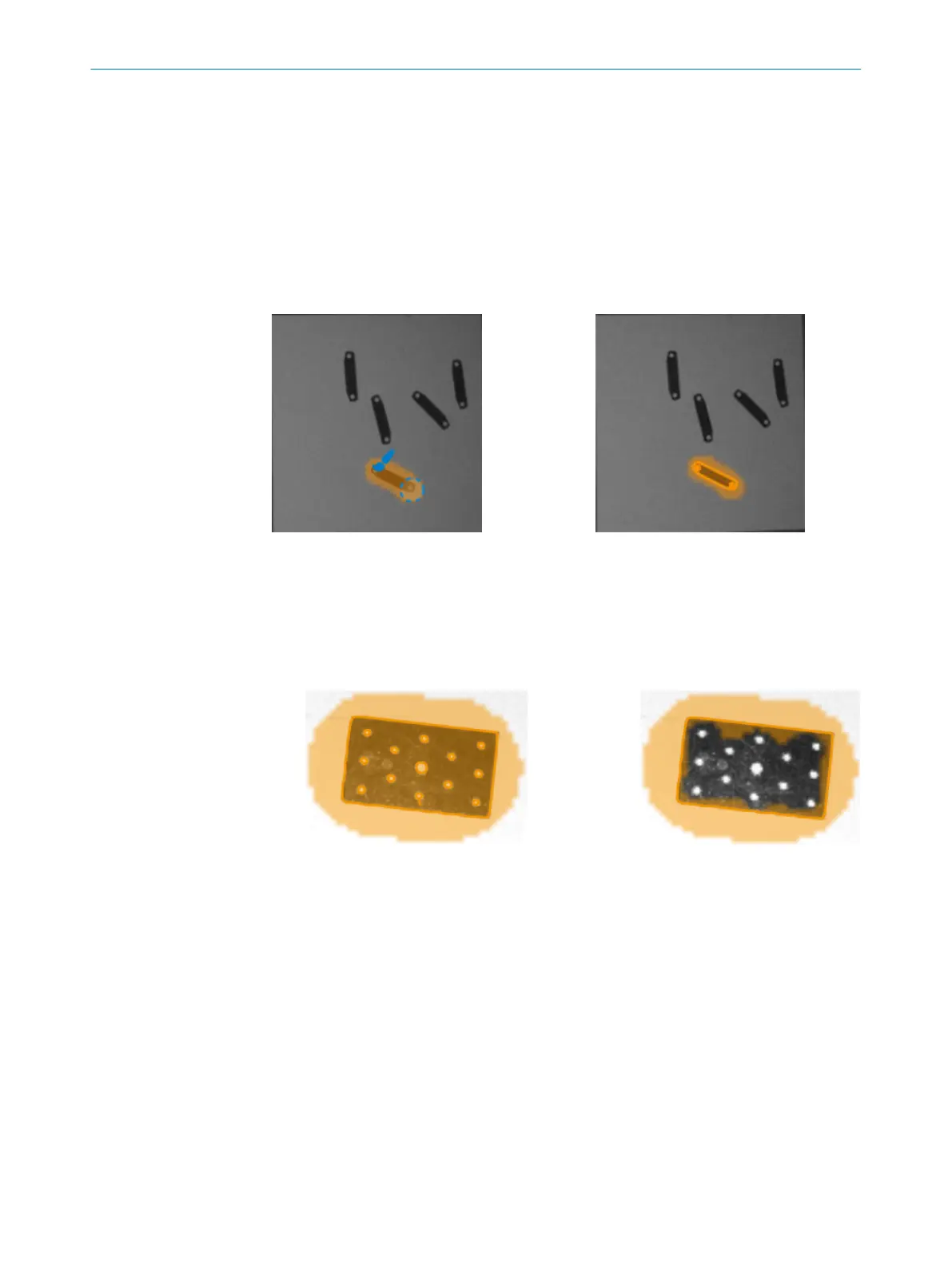
Figure 21: Draw a part shape region Figure 22: Highlighted part contours
•
If needed, click Eraser to manually erase regions that do not belong to the refer‐
ence part. See figure 23.
°
Use the mouse scroll wheel or the + and - keys to adjust the size of the Eraser
tool.
°
Zoom by pressing Shift+Up arrow or Shift+Down arrow
°
Pan the zoomed view with the arrow keys.
Figure 23: Left image: Creating a part shape region over the entire part. Right image: Using
the eraser to exclude holes from the part shape region.
Draw a gripper clearance region
The gripper clearance regions define areas that must not be blocked. Located parts
with something blocking the gripper clearance region, e.g., another part will be rejected.
Collision checks in gripper clearance regions are used if Reject colliding matches is ena‐
bled, see Gripper clearance.
1. Click Gripper clearance to select the gripper clearance region layer. The gripper
clearance region is blue.
2. Click Auto to automatically add a gripper clearance region surrounding the part
shape, or use the Brush and Eraser tools to draw a gripper clearance region.
Draw a job exclusion region
In a job exclusion region, a defined part of this job is never reported as a result.
OPERATION 7
8020736/1K3Z/2023-06 | SICK O P E R A T I N G I N S T R U C T I O N S | PLOC2D 4.1
49
Subject to change without notice