Chapter 4 Operating instructions
Flexi Classic
64 © SICK AG • Industrial Safety Systems • Germany • All rights reserved 8011509/YPP0/2015-10-26
Subject to change without notice
Special applications and
functions
Ensuring the protective function when a Flexi Classic system with single-beam
photoelectric safety switches is used
• Single-beam photoelectric safety switches may only be used as access protection in
accordance with EN ISO 13 855. Usage as finger and hand protection is not permissible.
• Interference beams (for example, direct/indirect sun irradiation, remote controls) are to
be prevented since they can reduce the availability of single-beam photoelectric safety
switches.
• The number of beams of the sender and receiver as well as the distance between the
beams must agree.
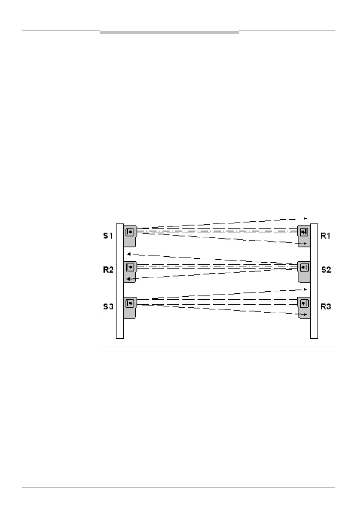
Mutual influence of single-beam photoelectric safety switches
• If several pairs of single-beam photoelectric safety switches are used, it is imperative
that the aperture angle of the sensors is observed to avoid the possibility of mutual
interference.
• If the senders are only mounted on one side, the light beams may not overlap on the
receiver side, i.e. the light beam of one sender may not reach two receivers.
• If the senders and receivers are mounted alternately, ensure that the light beam of
sender S1 cannot be received by receiver R3 and that the light beam of sender S3
cannot be received by receiver R1.
Mutual optical influence between cascades must be excluded.
Reflective surfaces that exist within the sending and receiving cones, placed or mounted
there can cause incorrect reflection and therefore non-detection of an object or a person.
All reflective surfaces and objects (for example material bins) must therefore be located at
a minimum distance (a) rotational-symmetrically around the optical axis between the
sender and receiver.
mutual optical influence
 Loading...

