EasyManuals Logo

SICK UE410-MU User Manual

SICK UE410-MU
124 pages
To Next Page IconTo Next Page
To Previous Page IconTo Previous Page
Page #85 background imageLoading...
Page #85 background image
Operating instructions Chapter 7
Flexi Classic
8011509/YPP0/2015-10-26 © SICK AG • Industrial Safety Systems • Germany • All rights reserved 85
Subject to change without notice
Application examples and
connection diagrams
7 Application examples and connection diagrams
By taking into account all the necessary boundary conditions and their evaluation in a
Failure Mode and Effects Analysis (FMEA), applications up to a maximum of SIL3
(IEC 61 508) can be achieved.
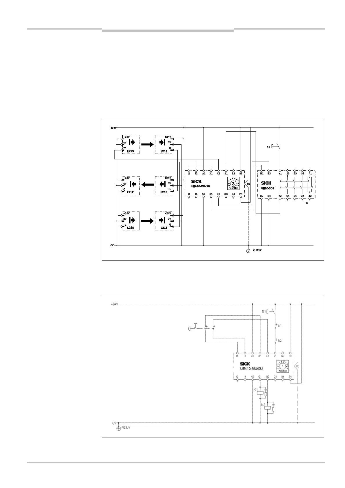
7.1 L21 on the UE410-MU/XU
Program 3.2 with restart interlock and EDM
7.2 Emergency stop on the UE410-MU/XU
Program 1 with restart interlock and EDM
Note
Fig.
41
:
Connection of t
hree
L21 to the UE410-MU/XU
Fig.
42
:
Connection of an
emergency stop to the
UE410-MU/XU

Table of Contents

Questions and Answers:

Question and Answer IconNeed help?

Do you have a question about the SICK UE410-MU and is the answer not in the manual?

SICK UE410-MU Specifications

General IconGeneral
Operating Voltage24 V DC
Safety outputs2
Response time≤ 20 ms
Protection classIP20
Housing materialPlastic
Safety Integrity LevelSIL 3
Performance LevelPL e
Number of Outputs2
MountingDIN rail
Supply voltage24 V DC
Current consumption≤ 100 mA
Output typeSemiconductor
Switching current≤ 0.5 A
ConnectionScrew terminals

Related product manuals