Chapter 3 Operating instructions
Flexi Classic
58 © SICK AG • Industrial Safety Systems • Germany • All rights reserved 8011509/YPP0/2015-10-26
Subject to change without notice
Product description
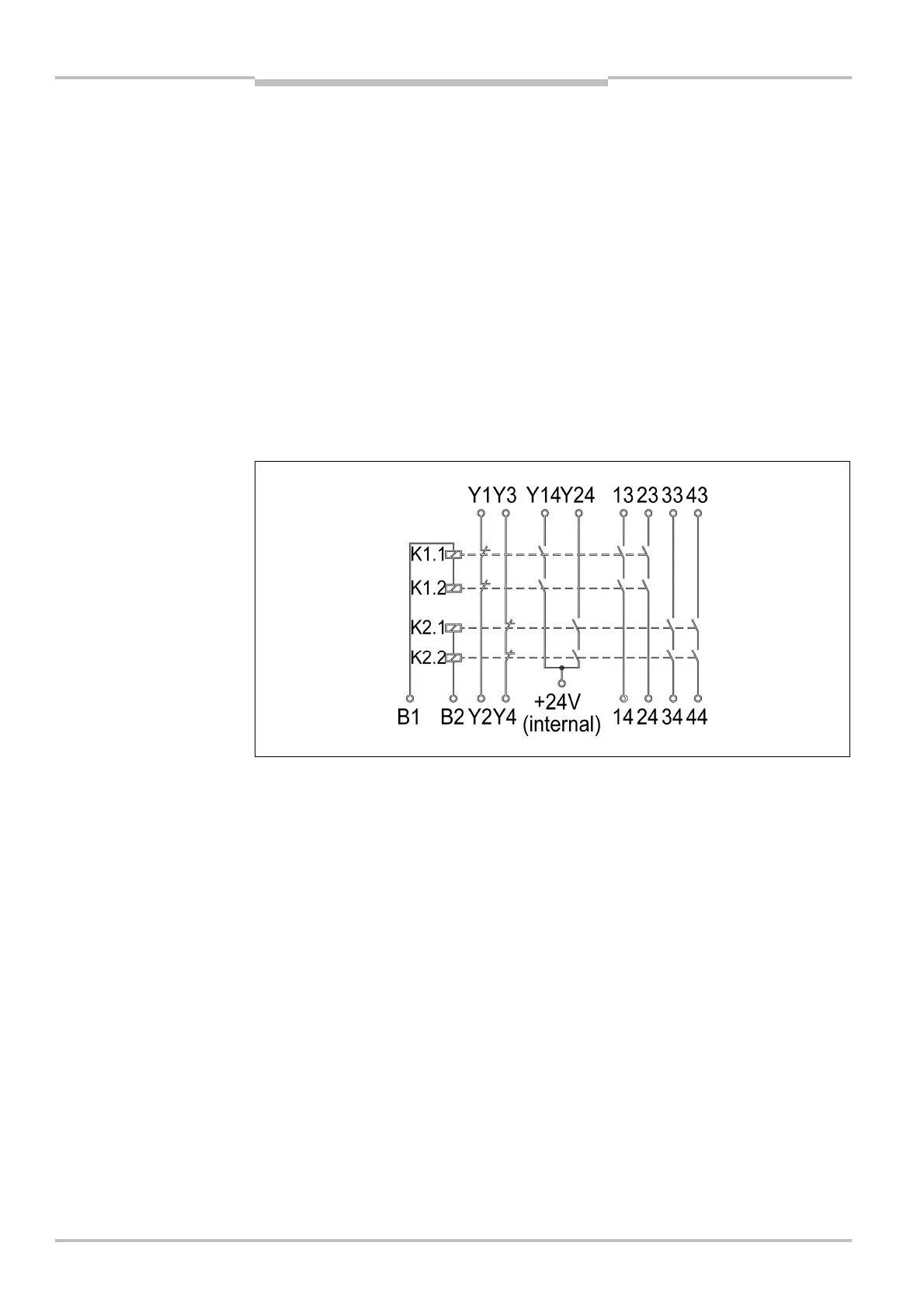
3.9.2 Output module UE410-4RO
The UE410-4RO has two control inputs (B1, B2). These inputs control two-by-two internal
relays that form two independent redundant shutdown paths.
Control input (B1) operates two internal relays and forms one redundant shutdown path
comprising:
• two “safe enable current paths” (13/14, 23/24), dual-channel and floating,
• one “safe enable current path” (Y14), dual-channel and not floating,
• one “external device monitoring feedback circuit” (Y1/Y2), dual-channel and floating.
Control input (B2) operates two internal relays and forms one redundant shutdown path
comprising:
• two “safe enable current paths” (33/34, 43/44), dual-channel and floating,
• one “safe enable current path” (Y24), dual-channel and not floating,
• one “external device monitoring feedback circuit” (Y3/Y4), dual-channel and floating.
The UE410-4RO therefore has twice the functionality of an UE410-2RO.
UE410-4RO
 Loading...

