Electrical connection
22 © SICK AG • Subject to change without notice • 8014865/ZUJ3/2018-11-29
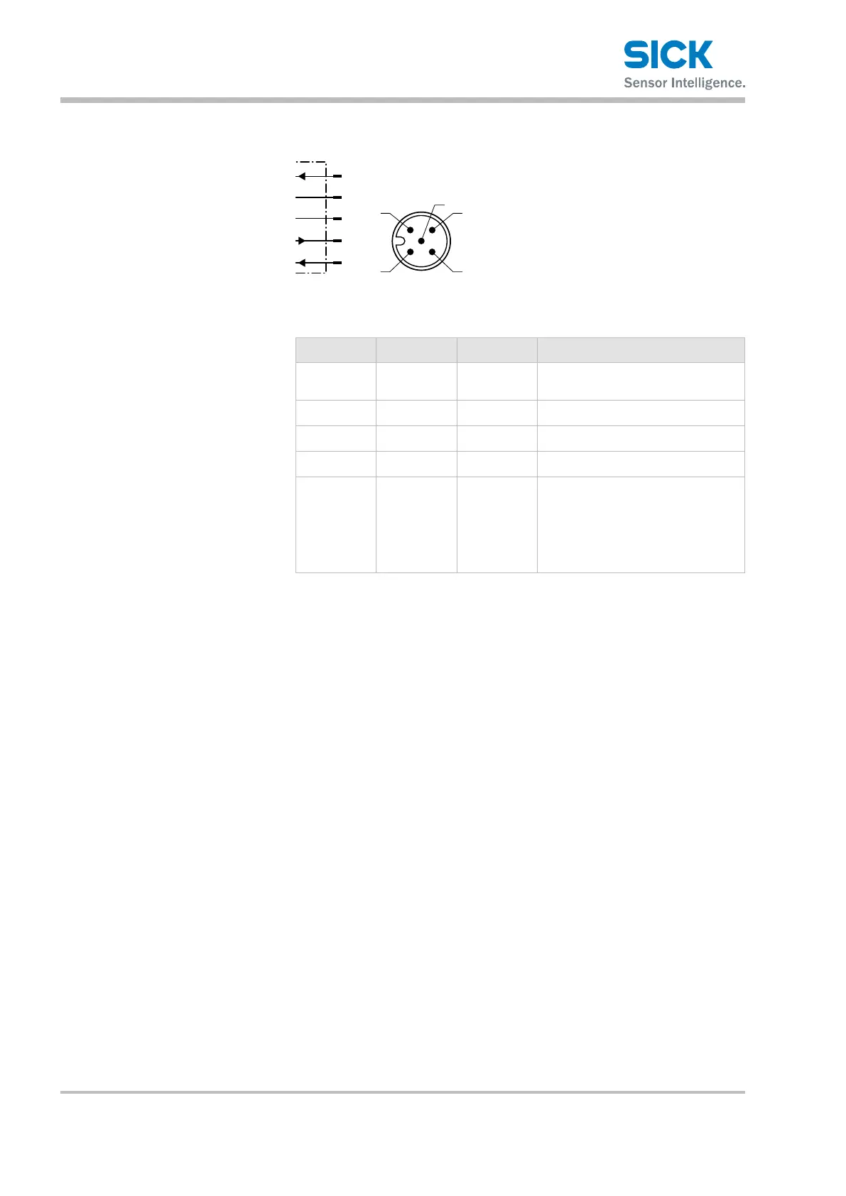
6.4.2 Ultrasonicsensorswithanalogoutputs
UM18-21xxx6xxx,
UM18-21xxx7xxx
L+
nc
1
4
brn
blk
Q
A
2
wht
3
M
blu
5
MF
gra
4
Fig. 7: UM18-21xxx6xxx (4 … 20 mA) and UM18-21xxx7xxx (0 … 10 V)
connection diagram, M12 plug, 5-pin, A-coded
Contact Marking Wire color Description
1 L+ Brown Supply voltage:
→ See Page 43, Chapter 11.3.
2 Q
A
White Analog output
3 M Blue Supply voltage: 0 V
4 Nc Black Not assigned
5 MF Gray Multifunction input/output for
• External teach
• Synchronization mode/multiplex
mode
• Connect+ communication
Table 5: Description of UM18-21xxx6xxx and UM18-21xxx7xxx plugs