8014865/ZUJ3/2018-11-29 • © SICK AG • Subject to change without notice 13
Structure and function
4 Structure and function
4.1 Structure and status indicators
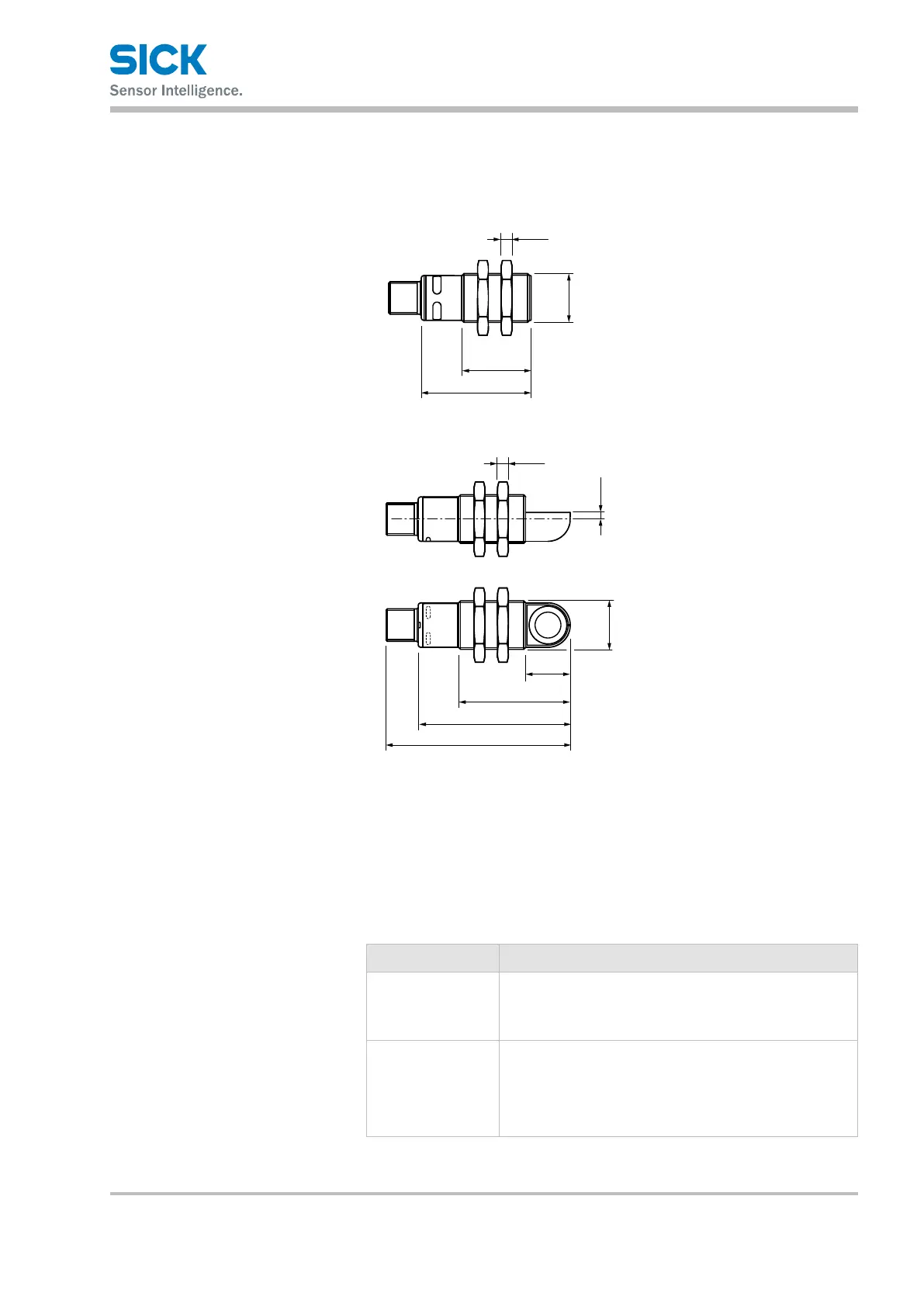
25.5 (1.00)
40.5 (1.59)
(0.16)
M18 x 1
2
3
4
All dimensions in mm (inch)
1
56.5 (2.22)
41.5 (1.63)
16
(0.63)
(0.16)
M18 x 1
3.4
2
3
4
68.5 (2.70)
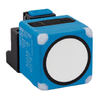
Fig. 2: Structure: top "UM18-2xxxxxxx1 ultrasonic sensor"
bottom "UM18-2xxxxxxx2 ultrasonic sensor"
1 Connection
2 Mounting nuts, width across 24 mm
3 Supply voltage active LED status indicator (green)
4 Switching/analog output LED status indicator (orange)
Status indicators (LEDs)
Status display Description
Green Supply voltage
• Green LED: Supply voltage on
• LED o: Supply voltage o
Orange
Switching/analog output
• LED orange: Switching output active/measured value
within analog output scaling
• LED o: Switching output inactive/measured value
outside analog output scaling
Table 2: Status indicators (LEDs)