8014865/ZUJ3/2018-11-29 • © SICK AG • Subject to change without notice 21
Electrical connection
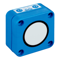
6.4 Connection diagrams
NOTE!
The lead colors specied in Sections 6.4.1 and 6.4.2
apply to SICK AG's preassembled cables. The lead
colors may vary for preassembled cables from other
manufacturers.
→ For preassembled cables, see Internet
"www.sick.com/en/um18", Accessories.
6.4.1 Ultrasonicsensorswithswitchingoutputs
UM18-21xxxAxxx
L+
Q/¯
1
4
brn
blk
nc
2
wht
3
M
blu
5
MF
gra
4
Fig. 6: UM18-21xxxAxxx connection diagram,
M12 plug, 5-pin, A-coded
Contact Marking Wire color Description
1 L+ Brown Supply voltage:
→ See Page 43, Chapter 11.3.
2 Nc White Not assigned
3 M Blue Supply voltage: 0 V
4
Black Switching output /
IO-Link communication
5 MF Gray Multifunction input/output for
• External teach-in
• Synchronization mode/multiplex
mode
• Connect+ communication
Table 4: Description of UM18-21xxxAxxx plug