Technical data
46 © SICK AG • Subject to change without notice • 8014865/ZUJ3/2018-11-29
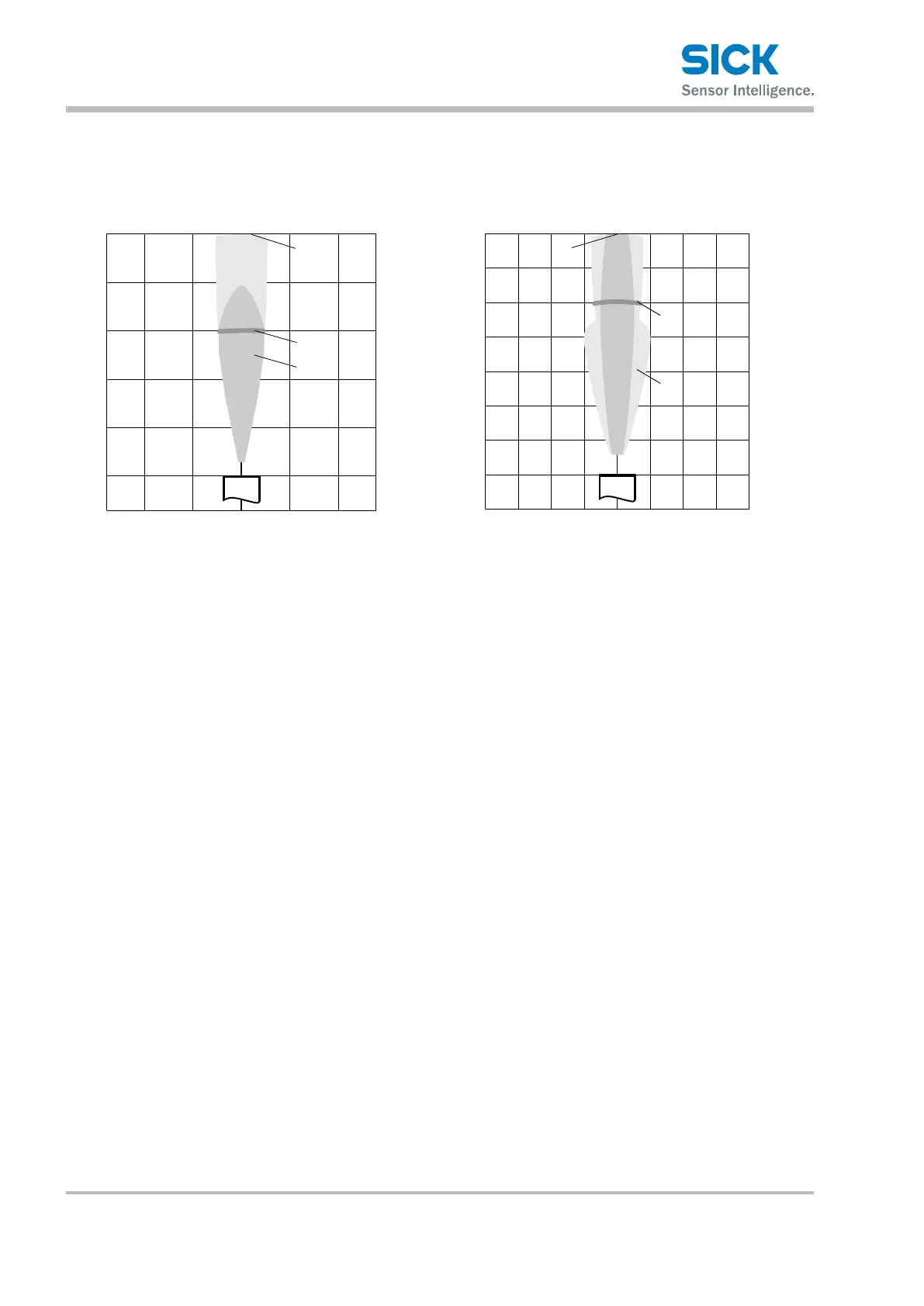
11.9 "Detectionzone"diagrams
UM18-217 UM18-211
0
50
250
150
200
100
100
(3.94)
50
(1.97)
0
Detection area in mm (inch)
Detection area in mm (inch)
50
(1.97)
100
(3.94)
5
3
2
1
4
100
(3.94)
150
(5.91)
150
(5.91)
Detection area in mm (inch)
100
(3.94)
50
(1.97)
50
(1.97)
0
Detection area in mm (inch)
0
50
(1.97)
150
(5.91)
100
(3.94)
200
(7.87)
250
(9.84)
300
(11.81)
350
(13.78)
3
4
5
2
1
Fig. 14: "UM18-217" detection zone
1 Detection zone depends on reection characteristics,
size, and alignment of the object
2 Limiting range
3 Operating range
4 Example object: aligned plate 500 mm x 500 mm
5 Example object: round bar with diameter 10 mm
Fig. 15: "UM18-211" detection zone
1 Detection zone depends on reection characteristics,
size, and alignment of the object
2 Limiting range
3 Operating range
4 Example object: aligned plate 500 mm x 500 mm
5 Example object: round bar with diameter 10 mm