SYSTEM DESCRIPTION 3
8026364 / V1-0/2022-03|SICK
Subject to change without notice
SUPPLEMENTARY OPERATING INSTRUCTIONS | VMS4200/5200
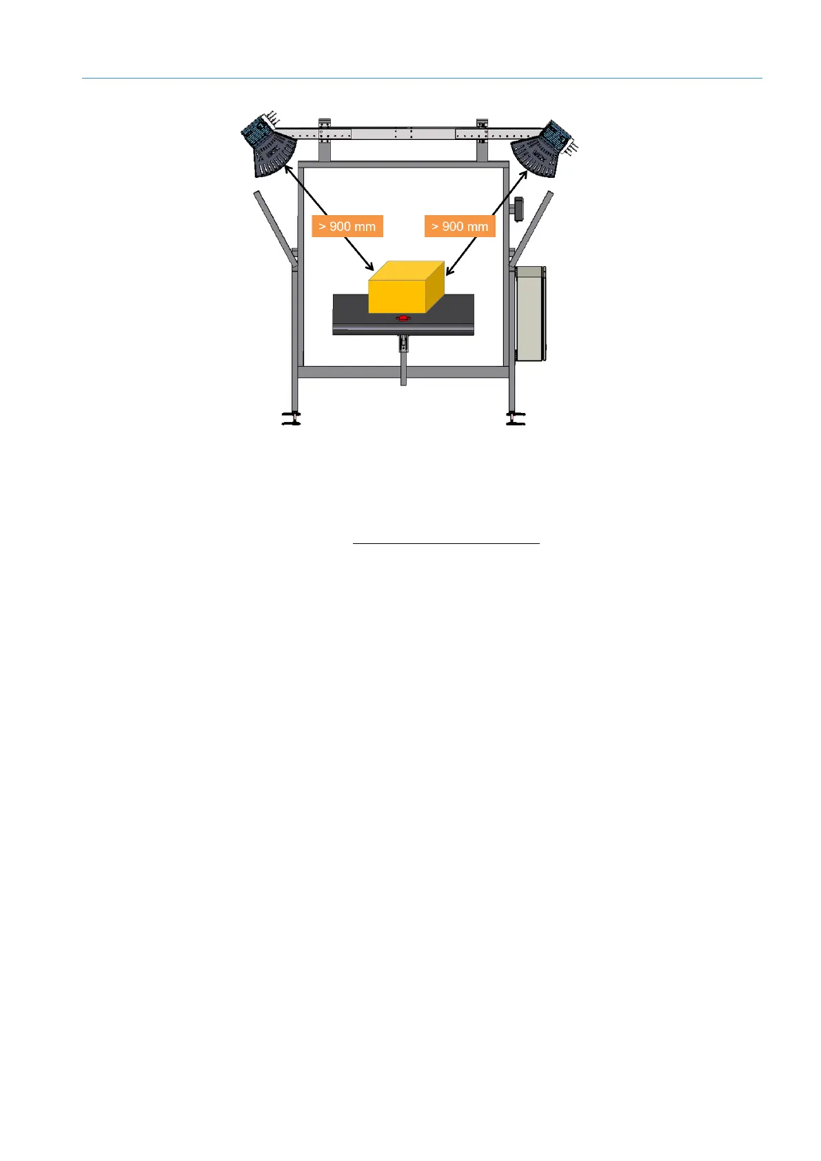
Fig. 44: Requirements for mounting the LMS4x21
▸
The 2D LiDAR sensors are mounted on the right and left of the conveyor in such a way
that they are free of vibrations and oscillations.
NOTE! Use the supplied mounting kit with telescopic tube and fastening elements.
See also section 4.1 Mounting 2D LiDAR sensors.
The telescopic tube must be mounted precisely at right angles to the conveying
equipment.
• The smallest permissible distance of the measuring object from the zero point of the
LMS4x21 is typically 900 mm. The zero point is marked on both the upper and lower
side of the housing of the LMS4x21.
▸
Observe the minimum distance of the LMS4x21 to the measuring object. The required
space for installation of the 2D LiDAR sensor is approximately 900 mm above the
tallest object.
▸
Maximum detection must be limited to a working sensing range of three meters.
Otherwise, it may not be possible to attain the specified scale interval value.
▸
Make sure that the LMS4x21 has a clear view of the conveying equipment.
• Ensure sufficient distance of the LMS4x21 from curves, induction lines, start/stop
areas, areas with upward and downward inclines, and breaks in the conveyor system.
• LFT measurements over the belt gap are not permitted.
Mounting the
LMX4x21
Optimizing the
scan result
 Loading...