EasyManua.ls Logo

SICK VMS4200 User Manual

SICK VMS4200
120 pages
To Next Page IconTo Next Page
Page #1 background imageLoading...
Page #1 background image
OPERATING INSTRUCTIONS
VMS4200/VMS5200 (Multicontroller)
Track and trace systems

Table of Contents

Other manuals for SICK VMS4200

Questions and Answers:

SICK VMS4200 Specifications

General IconGeneral
BrandSICK
ModelVMS4200
CategoryGPS
LanguageEnglish

Summary

About This Document

Purpose of Document

Describes the VMS4200/5200 multi-dimensional measurement system (Multicontroller).

Target Groups

Intended for qualified persons operating the VMS4200/5200 (Multicontroller).

Further Information

Provides details on local conditions and other relevant documentation.

Safety Information

Intended Use

Specifies the application of the VMS4200/5200 system for measuring objects on conveying systems.

General Safety Notes

Provides essential safety guidelines and precautions for operating the system.

Sources of Hazard

Details potential hazards from laser radiation, electrical voltage, and suspended loads.

Protective Devices

Describes built-in safety features like laser protective covers for safe operation.

System Description

Scope of Delivery

Lists the components included in the VMS4200/5200 system package.

System Components Overview

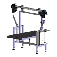
Identifies and illustrates the main devices and parts of the VMS4200/5200 system.

Operating Principle

Explains how the system measures objects using LiDAR sensors and different modes.

Legal for Trade Operation

Details requirements for operating the VMS5200 for billing purposes and verification.

Mounting

Mounting 2D LiDAR Sensors

Provides instructions for assembling and attaching the 2D LiDAR sensors to the frame.

Mounting Incremental Encoder

Details the procedure for installing the incremental encoder on the conveyor belt.

Mounting the Cabinet

Describes how to securely attach the system cabinet to the frame.

Electrical Installation

Connection Overview

Illustrates the electrical connections for the VMS4200/5200 system variants.

Voltage Supply Connection

Explains how to connect the system to the main power supply.

2D LiDAR Sensors Connection

Shows how to connect the LMS master and slave sensors to the system controller.

Commissioning

Switching on the System

Outlines the initial steps for powering up the system components.

Configuring System with SOPAS

Explains how to use SOPAS ET software for system setup and configuration.

Assigning IP Addresses

Details the procedure for setting IP addresses for system components.

Maintenance and Repair

Monitoring and Cleaning Work

Covers routine checks, visual inspections, and cleaning procedures for system components.

Replacing Components

Provides instructions on how to replace defective parts like LiDAR sensors or mirrors.

Fault Diagnosis

Fault Indications of Components

Lists common fault indicators for LMS4x21 and SIM2000 system controllers.

Checks on the SIM2000

Troubleshooting steps for trigger, encoder, and CAN cabling issues on the SIM2000.

Technical Data

Data Sheet

Presents detailed specifications for the VMS4200/5200 system, including ranges and scales.

Dimensional Drawings

Provides detailed drawings of the 2D LiDAR sensor and the system cabinet.

Disposal

Disposal Guidelines

Provides information on the environmentally sound disposal of electronic devices and components.