ELECTRICAL INSTALLATION 5
8022965-17I6/2020-03-19|SICK
Subject to change without notice
ORIGINAL OPERATING INSTRUCTIONS| VMS4200/5200 (Multicontroller)
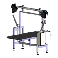
5.6 Connection for the LFT display (set up at the factory)
For the VMS5200 and VMS5200 (Multicontroller) system variants, the LFT display
is connected in the same manner to the system controller.
Fig. 70: Connection for the LFT display (set up at the factory)
Ethernet data cable
No. Connection on LFT display Port on Ethernet switch
1 ETHERNET (X118) 3
No. Port on Ethernet switch Port on SIM2000
2 4 X12
Voltage supply
No. Wire color Area on fuse block Connection
3
Brown F1_6A 15 +
Blue F1_6A 25 -
Tab. 16: Connection for the LFT display (set up at the factory)